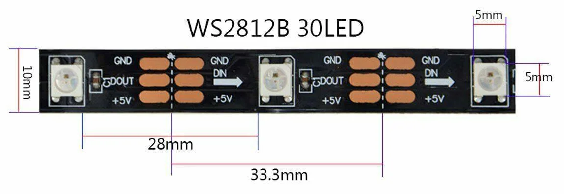
 Probably this question "how does it work" seems silly to many. The answer is almost obvious: an addressable LED strip consists of a plurality of “smart LEDs” connected in series. This can be seen simply by looking at the tape device. You can see individual microcircuits soldered to a flexible loop, you can see the connections: microcircuits are connected in series with only three wires, and two of them are power and ground. Only one wire transmits pixel color data. How is that? What is a smart LED?Next, I will talk about the data transfer protocol used in the LED strip based on WS2812B, and, moreover, I will almost create my own “LED strip chip” in the FPGA chip.So, the tape uses serial transmission through a single data signal.Bit zero is transmitted as a short positive impulse and a pause that is approximately two times wider than the impulse. The bit unit is transmitted as a wide positive pulse and a short pause:
 If there is no transmission of more than 50 microseconds, the tape goes back to its original state, ready to accept pixels starting from the first.Every 24 bits in a sequence is 3 bytes for three RGB colors. And in fact the sequence will be GRB. The high bit of G7 comes first.The sequence of the first 24 bits is one pixel, which will receive the very first LED in the tape. Until the first LED is saturated, it does not transfer data further to the next LED. After the first LED receives its portion of 24x RGB bits, it opens the transmission to the next. Primitively, one can imagine a sequence of LEDs as a cascade of jugs filled with water in succession: The
 first, then the second, then the third, and so on , will be filled in turn.Thus, I believe that the transfer protocol has been sorted out.Is it possible to try to design such a “smart LED” yourself? Of course, this makes little practical sense, but for self-education and broadening one's horizons, this is an interesting task. Let's try to describe the logic of the chip in the programming language Verilog HDL. Of course, this will not be a real chip design, there will be limitations. One of the most important limitations - I will need an external clock for my microcircuit. In a real smart LED, such a generator also exists, but it is already integrated into the chip.Let's start the Verilog module like this:
module WS2812B(
	input wire clk,
	input wire in,
	output wire out,
	output reg r,
	output reg g,
	output reg b
);
I think everything is clear here: the clock frequency of clk, the input and output signals of the “smart LED” in and out, and, of course, the output signals r, g, b through which I will control the real external LEDs in red, green and blue.I will capture the input signal in a two-bit shift register and from the current state in these captured bits I can determine the beginning of the positive edge of the signal in:reg [1:0]r_in = 0;
always @( posedge clk )
r_in <= { r_in[0],in };
wire in_pos_edge; assign in_pos_edge = (r_in==2'b01);
In addition, it is important to determine the status of the tape reset when the control controller pauses before starting a new transmission:localparam reset_level = 3000;
reg [15:0]reset_counter = 0;
always @( posedge clk )
if( r_in[0] )
reset_counter <= 0;
else
if( reset_counter<reset_level )
reset_counter <= reset_counter+1;
wire reset; assign reset = (reset_counter==reset_level);
Further, from a positive edge in_pos_edge it is necessary to withstand some pause in order to get the moment of fixing a new bit:localparam fix_level = 50;
reg [7:0]bit_length_cnt;
always @( posedge clk )
if( in_pos_edge )
bit_length_cnt <= 0;
else
if( bit_length_cnt<(fix_level+1) && !pass )
bit_length_cnt <= bit_length_cnt + 1;
wire bit_fix; assign bit_fix = (bit_length_cnt==fix_level);
The number of already received bits in the chip is considered as follows:reg pass = 0;
reg [5:0]bits_captured = 0;
always @( posedge clk )
if( reset )
bits_captured <= 1'b0;
else
if( ~pass && bit_fix )
bits_captured <= bits_captured+1'b1;
An important pass signal is introduced here, which just determines the redirection of the input stream to the output. After accepting the 24x pixel bit, the pass signal is set to one:always @( posedge clk )
if( reset )
pass <= 1'b0;
else
if( bits_captured==23 && bit_fix )
pass <= 1'b1;
reg pass_final;
always @( posedge clk )
if( reset )
pass_final <= 1'b0;
else
if( r_in!=2'b11 )
pass_final <= pass;
assign out = pass_final ? in : 1'b0;
Input out is multiplexed to the output out when the pass_final signal is one.Well, of course, we need a shift register, where the received 24 bits of the pixel are accumulated:reg [23:0]shift_rgb;
always @( posedge clk )
if( bit_fix )
shift_rgb <= { in, shift_rgb[23:1] };
reg [23:0]fix_rgb;
always @( posedge clk )
if( bits_captured==23 && bit_fix )
fix_rgb <= { in, shift_rgb[23:1] };
Upon receipt of all 24 bits, they are copied to the final 24 bit register as well.Now the matter remains small. It is necessary to implement a PWM (Latitudinal Pulse Modulation) signal to transmit brightness to real external LEDs according to the received RGB bytes:wire [7:0]wgreen; assign wgreen = { fix_rgb[0 ], fix_rgb[1 ], fix_rgb[2 ], fix_rgb[3 ], fix_rgb[4 ], fix_rgb[5 ], fix_rgb[6 ], fix_rgb[7 ] };
wire [7:0]wred; assign wred = { fix_rgb[8 ], fix_rgb[9 ], fix_rgb[10], fix_rgb[11], fix_rgb[12], fix_rgb[13], fix_rgb[14], fix_rgb[15] };
wire [7:0]wblue; assign wblue = { fix_rgb[16], fix_rgb[17], fix_rgb[18], fix_rgb[19], fix_rgb[20], fix_rgb[21], fix_rgb[22], fix_rgb[23] };
reg [7:0]pwm_cnt;
always @( posedge clk )
begin
pwm_cnt <= pwm_cnt+1;
r <= pwm_cnt<wred;
g <= pwm_cnt<wgreen;
b <= pwm_cnt<wblue;
end
That seems to be all.A small detail remains - how to experience it all?I took some simple motherboards with the FPGA MAX II (these are the Mars rover series cards) and flashed them all with the project with this Verilog code. There were already 8 LEDs on the boards, but they were all yellow. On each of the boards, I replaced 3 LEDs with R, G, B. I connected the boards in series and, moreover, connected them to a real LED strip. Thus, I lengthened the real tape with my homemade LEDs.This connection turned out like this: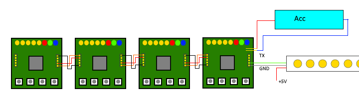 In reality, it looks like this:
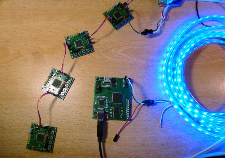 Now, applying a certain image to the tape, I see that my “smart LEDs” behave exactly the same as the real ones from the tape:It turns out that the logic I implemented in the FPGA is fully functional! As a first approximation, I was able to do something similar to a real smart LED chip.Actually, I like LED strips. On their basis, everyone can invent something of their own: intelligent lighting, screens, ambilight effects. Once I even implemented color music on a LED tape running FPGA. But that is another story .