Hello, Habr! I present to you the translation of the articles by Chris Svec, the original is here . Published with permission of the author under license CC-A-NC-ND .Embedded software engineering 101: introduction
I am launching a series of tutorials on firmware development. We will start by describing a simple microcontroller, and after you understand how it works, we will develop this to understand how it works with respect to complex systems such as Fitbit or Nest.I called this series Embedded Software Engineering 101, and it starts this week right here on this blog.Read on for further explanation and details.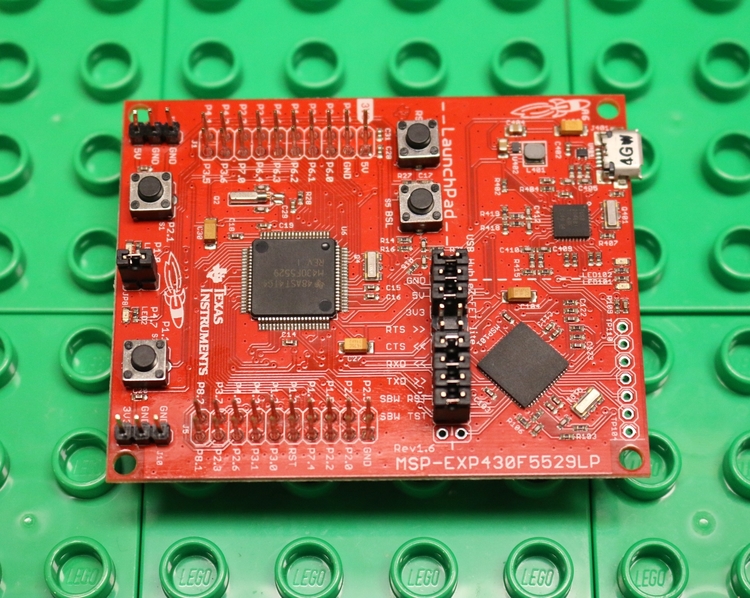 Some building blocks on other building blocks.I have been working with embedded systems and developing microchips for over 14 years. I like embedded systems - hardware, software, and the limitations that bind them together.Amateur electronics and ideas such as Arduino , Adafruit and Sparkfun made it possible to easily throw something from hardware and software over the weekend (or a month, or a semester), creating something new, interesting and can even be useful.It's great! Giving people the opportunity to create is an amazing thing; if I wanted to express myself harshly, I would aspirationally call it "democratizing technology."Most amateur projects are one-time. You collect something, make it as good as you have enough time or energy, and move on.I spent my career on the opposite end of the spectrum - creating products that are hundreds of thousands or millions or more copies - and this requires a completely different way of thinking and a systematic approach.I want to teach people how to write firmware for these kinds of systems. I have long nurtured this idea for the Embedded Software Engineering 101 course / guide / book / blog, and thanks to the Embedded.fm blog, I am starting to implement it now.I am a person of a fundamental type, so my plan is to start with the basics, with a simple description of a simple microprocessor, and develop this foundation until you understand how a relatively complex embedded system works.My goal is that by the end of this cycle you can figure out how Fitbit works, a Nest thermostat, or a similar embedded system. You can start working with embedded software systems using professional experience.Embedded Software Engineering 101 is designed for:
- University graduates in the field of computer science, computer engineering or electronics, interested in embedded systems.
- Amateur electronics enthusiasts who want to understand more deeply how their system works on Arduino and find out how they move on (and whether it is necessary!).
- , , .
- , , -.
What do I mean by saying that I am a “person of fundamental type”? Richard Feynman , a Nobel Prize-winning physicist and excellent storyteller, put it in the best possible way: “What I can’t recreate, I don’t understand.”So, I’m not Feynman, but I’m sure that the best way to understand the system is to start with the basics. Armed with this understanding, you can create simple embedded systems with simple software. And having understood at first a very simple program, you can develop it by creating more complex software as experience grows.The basics in the first place - this is of course only my personal conviction. Many people made useful things with Arduino without understanding any of the basics. This series of articles is for those who still want to understand the basics and everything that is built on them.Of course, we must ask ourselves - where is the right level to start with these very “basics”? Transistors and logic gates? No, this is too low to start with firmware. Connect to common sensors? No, this is too high a level, it takes too much knowledge to start with this.I think the right level of basics is the built-in microprocessor. It is not necessary to understand physics or electronics in order to use the built-in microprocessor; it is also not necessary to be an expert in programming.So this is where we will begin in the next article.Prejudice Warning: In a past life, I was an architect / processor developer. Starting this cycle by understanding how the CPU works may not be the best way to understand embedded systems, but that’s how my brain works. Be sure to try other courses / manuals, etc., if you do not understand this after several articles.Embedded software engineering 101: microcontroller basics
We will begin our journey of Embedded Software Egineering 101 with a modest microcontroller. A microcontroller (or microprocessor) is the main building block of all computing systems, embedded and others.MK seems rather complicated, but it consists of three simple things: instructions, registers and memory. Instructions are those things that the microcontroller knows how to perform. A simple MK is able to perform not so much - it can have, for example, 20 or 30 instructions. Later in this cycle I will use the MSP430 microcontroller from Texas Instruments, which has only 27 instructions. Just a photo of MK (TI MSP430F5529)These 27 instructions are the only things the MSP430 can do. He can add two numbers, subtract another from one number, move numbers from one place to another, or perform 24 other simple operations. 27 operations may not seem enough to do anything useful, but in reality they will be enough in excess to carry out any conceivable program.Well, that means the microcontroller has instructions that do something with numbers. But where are these numbers? Registers and memory! Instructions operate with numbers that are stored in registers and memory.Registers are a very fast repository containing numbers that operate on instructions. You can think of them as a notepad used by instructions. MK contains few registers, usually 8-32. For example, the MSP430 has 16 registers.Memory is also storage for numbers, but it is much larger and slower than registers. The microcontroller can have 64 kB, 256 kB or even more than 1 MB of memory. MSP430F5529 has about 128 kB of memory; this is more than 8,000 times the number of its registers!Before we begin to look at examples, I urge you to get a piece of paper and a pen or pencil and study these examples as you read. It’s more difficult to study them on paper than just reading what I wrote. Thus, you will carefully approach the process, and the chances of memorizing the learned will be higher.Let's look at a fictional, but characteristic example of a microcontroller.Let’s say our MK has 4 registers and 8 memory cells. Registers are usually called creatively, for example, “R0”, “R1”, etc., and we will do the same. Memory cells are usually referenced by their numbers, also called memory addresses, starting from numbering 0. This is how our registers and memory will look:
 And now I will put some values in them:
 Now, our fictional microcontroller needs some instructions.The set of instructions that MK knows is called its set of instructions. Let’s say in the set there will be three instructions: ADD (add), SUB (short for “subtract” - subtract) and MOVE (move). The instructions must get the numbers from which they operate from somewhere, and also put their results somewhere, so some of them contain information about where the input and output data are.For example, let our ADD instruction have two sources and one data receiver, and all of them must be registers. The manual may describe this instruction like this:
ADD regist, regPrm
The ADD instruction adds the value of the reg reg register to the value of the reg reg register and stores the result in the reg reg register
Summary: regPrm = regIST + regPrm
Example: ADD R1, R2 performs the operation R2 = R1 + R2
It is generally accepted in the instructions to use one of the sources also as a receiver, as the ADD instruction does, using regPrm as the source and receiver of data."ADD R1, R2" is an assembler language for a microcontroller, it is a native programming language MK.Let's define SUB in the same style:SUB regist, regrpm
The SUB instruction subtracts the value of the registr register from the value of the regprm register and stores the result in the regprm register
Summary: regPrm = regPrm - reggist
Example: SUB R3, R0 performs the operation R0 = R0 - R3
Finally, let the MOVE instruction have one source and one receiver, and either:- both arguments are registers, either
- one is a register and one is a memory location.
The instruction set guide will read:1. MOVE register, register
2. MOVE register, reg
3. MOVE register, rem
The MOVE instruction copies the data from the argument East into the argument Prm.
Summary: There are three types of MOVE instructions
1. regPrm = regist
2.regPm = memist
3. memPm = reg
Example: I will show examples of the MOVE instruction later in this post.
One note about the word “move” used for this instruction: most instruction sets use it, although in reality the data is copied, not moved.The name “move” may give the impression that the operand source of the instruction is destroyed or cleared, but in fact it remains alone, only the receiver is modified.Let's walk through a few examples using our fictional microcontroller.At the start, our registers and memory look like this:Now we execute the following instruction on the MK:ADD R1, R2
It takes the value of R1, adds it to the value of R2, and stores the result in R2. The processor executes most of the instructions in one operation, but I will split the execution of each ADD, SUB, and MOVE instruction into several steps with the "=>" arrow leading through replacements (register / memory => value):R2 = R1 + R2 =>
R2 = 37 + 100 =>
R2 = 137
After executing this instruction, the memory is unchanged, but the registers now look as follows, with the changed value written in red: Note that R1 is unchanged; only the receiver register R2 has changed.Next let's try the SUB statement:
SUB R3, R0
She takes the value of R3, subtracts it from the value of R0, and stores the result in R0:R0 = R0 - R3 =>
R0 = 42 - 2 =>
R0 = 40
After executing this instruction, the memory is unchanged, but the registers now look like this: Finally, let's try a couple of versions of the MOVE instruction:
MOVE R2, R0
This MOVE instruction copies the value of R2 to R0:R0 = R2 =>
R0 = 137
And now the registers look like this: Next, we copy the register into memory:
MOVE R3, [3]
This MOVE instruction copies R3 to memory location 3. The square brackets in our instruction set are the memory cells.[3] = R3 =>
[3] = 2
The registers are unchanged, but the memory changes: And for our last example, we copy the value from memory to register:
MOVE [6], R0
Here, the value of memory cell 6 is copied to the register R0:R0 = [6] =>
R0 = 1
The memory is immutable, and the registers now look like this: Believe it or not, but if you understand most of what we just discussed about instructions, registers and memory, then you understand the basics of microcontrollers and assembly language.Of course I have omitted many details. For example, how does MK get instructions to execute?Are there any more interesting instructions than just simple math and copy instructions? Is memory the same as RAM or flash, or not?We will answer these questions in the next article.