In the first part, we put together a machine with the logic of the game. More precisely, not the whole game, but only the movement of the snake itself. In this final part, we will figure out how to connect the screen and finish the whole circuit. High Resolution - Click To Click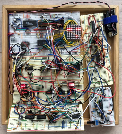
Draw a tail
We already have a head that runs alone on the 8 × 8 field, now we need to draw a tail. This is not one point, but a lot, and we simply cannot transfer the coordinates (X, Y) to the decoders.Usually on such matrices as ours, a “ dynamic indication ” is used, and the line-by-line version : when in turn the contents of each row as a whole are displayed. In our conditions, for this we will either have to store somewhere all 64 bits, or in some complicated way to calculate the value for each line. But there is another option for indication, it is also quite dynamic in the sense that not all points light up at the same time. We can use something like a “ vector display»- display each point in turn, giving its coordinates to the screen. At each particular moment in time, only one pixel will burn, which we will drive across the screen.Since the number of points with us can be different (depending on the length of the tail), the brightness of the resulting picture will also change with the course of the game and the growth of the snake itself. To prevent this from happening, we will reserve a fixed number of frames (10 = 1 frame for the head, 1 for the apple and 8 for the tail) and we will turn off the screen for unnecessary points. A - apple, H - head, T # - tail cells. Drawn in wavedrom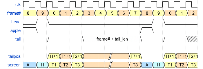 To display, we also need an automaton. This machine will have several parts: one of them is a frame counter, which will simply bypass 10 states in a circle. Let us take IE18 and some logic for these purposes.
 The simplest thing is to get the head out, in this frame we just turn on the screen and feed on the x / y bus the value that the automatic machine gives us. To do this, use the AP6 buffer (you can take AP5, but it does not have such a convenient pinout).Next we need to draw a tail. To do this, we will remember in our state what we just painted. Add the tail growth direction to it (using the schemefrom the previous part) and display. To know that we need to output the tail, we simply compare the frame number with the tail length using the 4-bit comparator SP1 (U13). We will store the previous coordinates in the 8-bit register IR37 (or IR27, they just ended ...), and for new ones we use EEPROM, the table for which we already generated in the first part. The direction of the desired section of the tail will be taken from the game machine using the KP15 multiplexers by applying the frame number to the address inputs. And we must not forget that we keep the direction of the head, which is opposite to the direction of the growth of the tail, which means that one of the components must be inverted. Fortunately, you won’t have to install a separate inverter, because KP15 has an inverse output. Total:
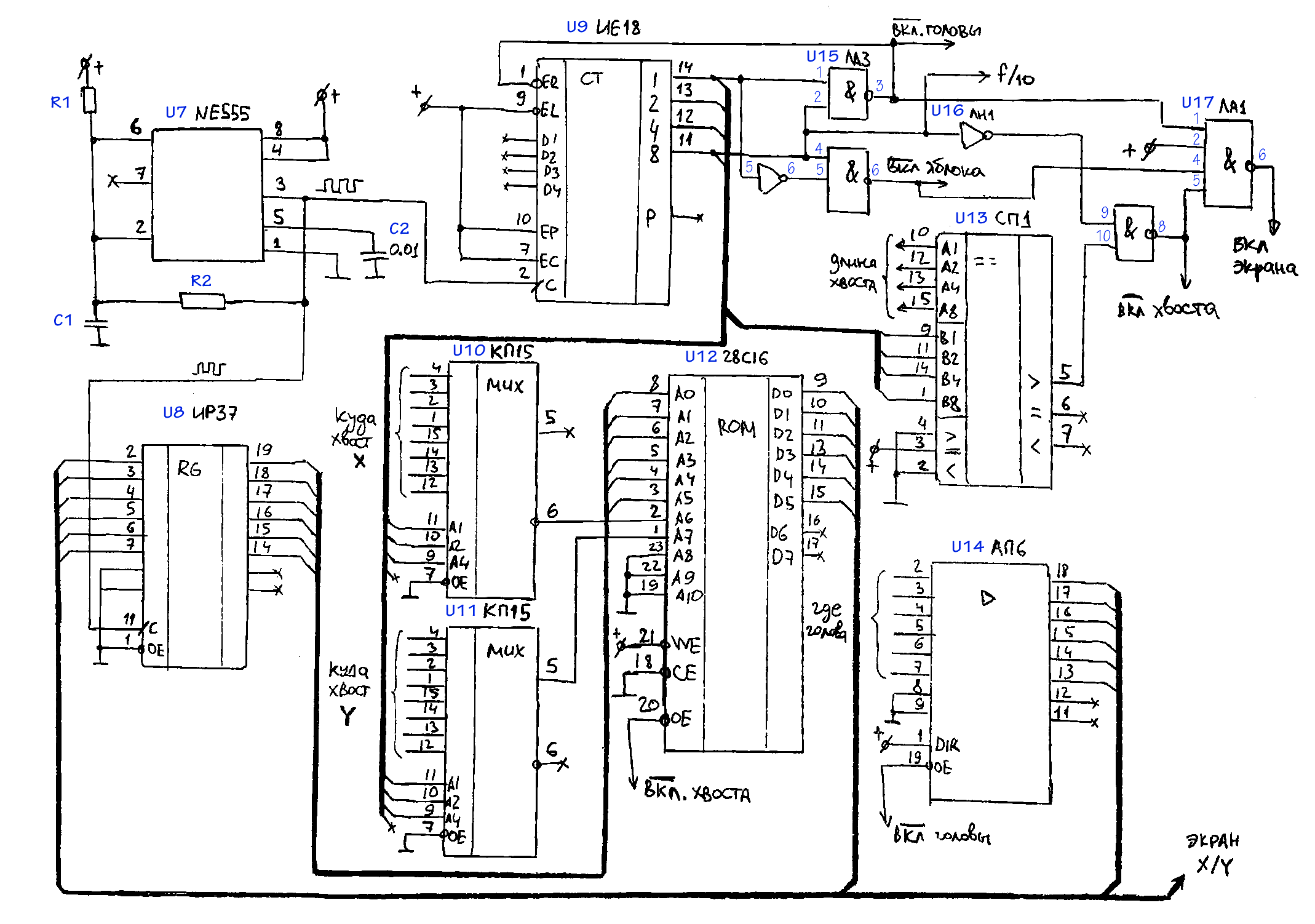 The machine turned out a little more confusing, but, nevertheless, the principle of operation is the same as that of everyone else.
An Apple
This is the most "dirty" part of our scheme. Firstly, because it requires a random position of the apple, and our machines do not have a drop of randomness. Secondly, we need to throw the signal of eating an apple from one machine to another, while the machines have a different clock signal. In an intelligent way, this is called clock domain crossing, but we will make a simple crutch.Where to get random? You can come up with a pseudo-random generator, but this will require a non-trivial amount of logic. Another option is to take a clock with a different frequency, preferably not very stable, but our NE555s do not differ in stability anyway. In the multivibrator circuit, you can add some noisy or non-linear elements to your taste (I added in series with a JFET resistor with a dangling shutter in the air). We will receive a random coordinate and store it in a 6-bit counter. There are no ready-made 6-bit chips, so let's connect two IE10 cases: In the same node, we will put a buffer to display the apple on the screen by the enable signal. And also a comparator in order to understand that what is now displayed on the screen coincides with the apple (two SP1). We will not only compare the apple with itself, for this we will use the 4th bit of the comparator and give it a permission signal on one side and one on the other.And here a dirty hack awaits us: depending on the series of the microcircuit, the delay of the resolution signal, the stray capacitance of the breadboard and the phase of the moon, the comparator may turn on a little earlier than the U23 driver turns off. More clearly what is happening:
 Due to the selected synchronization scheme (about it later), such a glitch will interfere with us. It would be correct to suppress it with the help of a delay, for example from several inverters, or even spread the inclusion and comparison into different phases. But I was already tired enough and just crushed it with a C5 capacitor, since this is the dirty part of the circuit :)
Clocking and picking a new apple
The main U7 generator clocks frames, we have 10 of them, then we will divide this frequency by 16 using another IE10 counter (U19) and use it to clock the steps. The signal that the head coincides with the apple appears on only one frame out of 10 and will not last until the front of the pulse switching the frame. Here we need a synchronization circuit. I decided to take the simplest option: we will inject the signal into the asynchronous input of the trigger, and we will reset it to each new step of the receiving machine. At the output of the trigger, we get a signal to add another tail cell (U6), as well as to start the counter that stores the coordinates of the head (U21, U22), this will generate a new, possibly random, apple.
Whole circuit
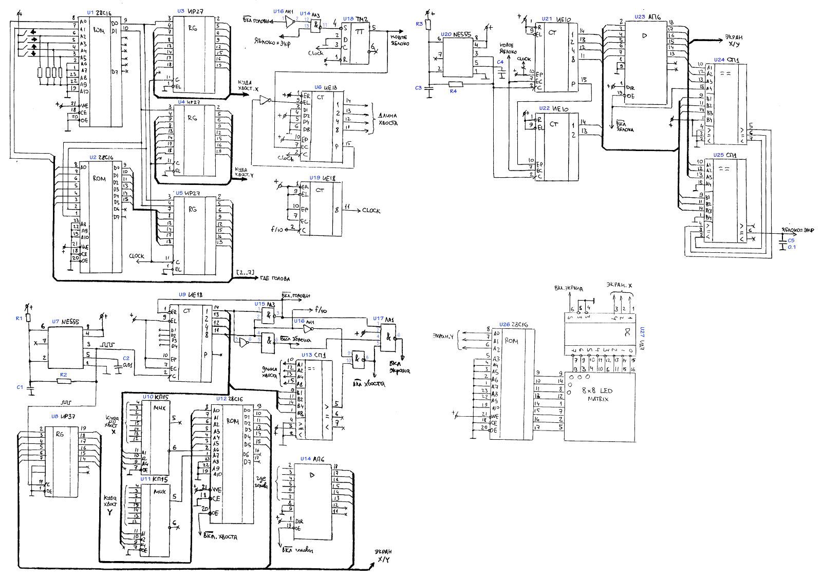 Great click-through scheme. And how it looks on the breadboard - at the beginning of the article
Parts and Components
breadboards
You can take Chinese development boards from Ali, but then problems with bad contacts will take much more time than directly assembling the circuit. Good boards are recommended by Ben Eater, these are boards BB830 (white) or WBU-202 (yellow). A set of wires is also best to take Wisher (WJW-60B), and any Chinese set, even the cheapest one, will be used as soft.microcircuits
I tried to assemble on the most popular domestic series, KP1533. In the West, this is the 74ALS series, but there it was not at all popular. In this scheme, there are no critical parameters for timings or load capacity, so you can safely take a series of K555 (74LS) or even K155 (SN74). Of the imported ones, you can take 74HC (but then for compatibility levels you will have to take almost all the chips from this series) or 74HCT, which is fully compatible with TTL and CMOS series.Finding domestic microcircuits proved to be a daunting task: no one needs them in popular online stores and sold out all the remnants a long time ago. I collected some chips in local offline stores, others had to be ordered on the Internet, but many suppliers are not interested in tinkering with small orders, so it was still fun ...The resulting BOM turned out like this (through a slash, possible replacements are indicated):──────────────────────────────────────────────────────
│ 1× *1 74*04
│ 1× *3 74*00
│ 1× *1 74*20
│ 1× *2 74*74
│ 2× *6 74*245 / *5 74*244 ( )
│ 3× *1 74*85
│ 2× *15 74*251 / *7 *151
│ 1× *18 *163
│ 4× *18 *163 / *10 *161
│ 3× *27 74*377 / *37 74*574 ( )
│ 1× *37 74*574 / *27 74*377 ( )
EEPROM │ 3× AT28C16 / CAT28C16
│ 1× *7 74*138 / 4 74*155 ( )
│ 1× 5611 CD4028 ( ) / AT28C16
| 2× 10061 NE555
──────────────────────────────────────────────────────
Total
I hope you liked this scheme and, perhaps, someone will raise a hand to repeat it, or do something even more interesting)) Youcan watch the video on YouTube:in the comments to the previous part, we advised filtering on the LED matrix, this is a very good thing, but in dim lighting you can do without it.You can download the archive with the EEPROM circuit and dumps here .
Used materials
1. Harris & Harris's book that never tires of recommendingYuripanchul- for general guidance.2. Reference Biryukova S.A. - to search for pinouts of specific microcircuits.both books can be found in PDF, but the paper version is nicer3. Ben Eater 's website and its YouTube channel are for inspiration))4. Wavedrom is for drawing diagramsTo everyone who has read to the end, thanks for attention!