At leisure, my son and I study digital electronics. Recently, we got to the chapter on finite state machines. This topic is full of typical tasks, such as a semaphore or a vending machine. But they are all dull and too simple, and some are generally, frankly, far-fetched. After studying simple examples, I wanted to do something more interesting and complex. The classic game “snake” caught my eye (my son played it on the phone), and I suggested making it on state machines. After all, the state of the game is quite final (especially if you confine yourself to a small field), and from the inputs there are only 4 buttons. And this is what we got.The game Snake (she is a snake, python, boa constrictor, etc.) is widely known to everyone. She comes from the distant 70s, but I will not repeat her story, which you can read on Wikipedia or many articles on Habré. The game has fairly simple rules and at the same time addictive gameplay)) Thanks to this, it is often used for tutorials or code samples . In high-level programming languages, making such a game is easy enough. But in more limited conditions, the most interesting begins, for example, an implementation on LabVIEW . There are also many options on FPGA: link 1 , link 2 , link 3, Link 4 . But there has not been a single option on separate TTL-chips of standard series. So that’s what we’ll do.It would seem that FPGA solutions are the closest for us, and you can borrow a lot from there? But in all the options that I looked at, they are easily scattered in registers left and right. For example, very often a separate bit or number is allocated for each field cell. We cannot do this with loose powder, because each new register is a separate microcircuit that needs to be placed somewhere, and then connected. Therefore, we cross out all the experience accumulated by other developers and will do everything from scratch. As a bonus, we will collect everything on domestic (and better - Soviet) chips of the k555 / kr1533 series, with the exception of ROMs, which will have to be taken fresh.Formulation of the problem
We will have such restrictions: a field of size 8 × 8 cells (Chinese LED matrix ), a tail length of 8 cells. A snake can pass through walls, but we will not process the intersection with the tail at first (in order not to complicate the design, you can add this later). To describe the entire state of the game we need:- Head position (X = 0..7, Y = 0..7, 6 bits)
- Direction of movement (↑ ↓ ← →, 2 bits)
- Apple Position (X, Y, 6 Bit)
- Tail Length (0..7, 3 bits)
- The position of the tail cells (from 0 to 7 pieces of 6 bits each)
In total, 65 bits are obtained, even if we take registers of 8 bits each, only 8 such microcircuits (and one more trigger) are needed to store the state, this is quite a lot.But the tail cannot be located wherever it wants, it "grows" from the head. Therefore, we can store not the full coordinates of each section of the tail, but only the direction in which direction from the previous cell (or head) it needs to be drawn. Then, instead of 6 × 8 = 48 bits, we need 4 × 8 = 16 bits, and this is a saving of as many as four register cases!Automatic machines
Let's try to do everything on machines similar to Moore or Miles. To implement such an automaton, it is enough to have a bit of state memory (register) and combinational logic to switch between them. Wikipedia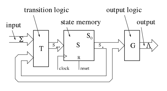 pictureUsually a state machine is described as a graph of states and transitions between them. Sometimes it’s more convenient to make a table of transitions to a new state, the simplest example (from Wikipedia):
 You can find more information and beautiful pictures, for example, in this article on Habré
Small digression, , . , ROM , ROM.
( , ).
, , .

, « » .
A snake of various states (if you do not take into account the position of the apple) can have 2 ^ 8 + 2 ^ 10 + ... + 2 ^ 24 ≈ 32 million. It is not possible to write them in the table, and even more so to draw a transition graph. But most of the transitions are quite the same (the head moves only one adjacent cell, and the tail moves one section per turn). In this case, we can not describe each individual state, but formulate a new state as a function of the previous one. Moreover, we can divide the whole game into several parallel automata: 1) an automatic machine of direction, 2) an automatic machine of position of the head, 3) an automatic machine for the tail. And to set each of them as it will be more convenient:1) , │
────────────────────┼───────────────────
← ←/↓/↑ │ ←
← → │ →
↑ ↑/←/→ │ ↑
↑ ↓ │ ↓
...... │
2) ,  │
  ─────────────────────┼──────────────
   ←             (x,y) │ (x-1, y)
   →             (x,y) │ (x+1, y)
   ↑             (x,y) │ (x, y-1)
   ↓             (x,y) │ (x, y+1)
3) ,                       │
  ─────────────────────────────────────────┼──────────────────────────
   ←            (t1,t2,t3,t4,t5,t6,t7,t8)  │ (←,t1,t2,t3,t4,t5,t6,t7)
   ......                               │
Direction
Let's start with the directional machine. If you think carefully, you can assemble it on a separate logic. But, since the task as a whole is already rather big, I decided that it would be easier to make a lookup table from EEPROM, and write the transition table manually. It will have 6 inputs, which means only 64 values, which we can simply drive into the hex editor.
Head
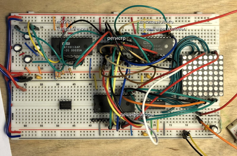
For a head position machine, writing such a table will be much more difficult. But it essentially contains only 2 operations: +1 and -1. They can be implemented on a 4-bit adder K155IM6. For +1, we will add our coordinate with b'0001, and for -1 with b'1111 (which actually is -1 in the additional code ). We will need two adders (for x and y), a bit of logic, and we will store the state in the 8-bit register IR27 (we still need a lot of them):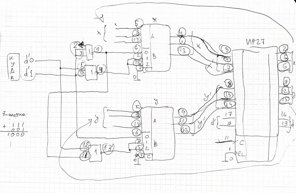 Let's assemble it on the board, and for verification we will immediately connect the LED matrix with two decoders. The decoder with inverse outputs is ID7, and for the direct one it would be possible to take K561ID1 (CD4028), but I didn’t have it at hand. Another option is to take 8 transistors as keys, but I did not want to do this, so I had to stupidly spend another EEPROM (writing only 8 cells there). The logic of the new head position on a separate board on top Another digression
 Let's take a short break and save the breadboard (and a few chip cases). We will again take advantage of the fact that any combination circuit can be replaced by a LUT by writing the table to ROM. But how to do this for such a large table? We will use another trick - we will do the opposite: replace the EEPROM with our logic circuit and put it into the programmer. Unused legs are connected to the ground through resistors. (This could not be done if you delve into the settings of the programmer)
Now we will read our logic diagram as ROM and get a table. We write it with the same programmer into a real EEPROM, which we put instead of a circuit of separate elements.
Let's take a short break and save the breadboard (and a few chip cases). We will again take advantage of the fact that any combination circuit can be replaced by a LUT by writing the table to ROM. But how to do this for such a large table? We will use another trick - we will do the opposite: replace the EEPROM with our logic circuit and put it into the programmer. Unused legs are connected to the ground through resistors. (This could not be done if you delve into the settings of the programmer)
Now we will read our logic diagram as ROM and get a table. We write it with the same programmer into a real EEPROM, which we put instead of a circuit of separate elements.
Tail
The tail has a length (in our limitations) from 2 to 8 cells. To store this length, you can use a conventional counter with an account resolution input. In fact, it will be the same finite state machine, in which the new state S 'will be equal to S + 1 or just S (if the account is prohibited). The tail itself (or rather, the direction where it grows) we will store in two registers of 8 bits. Theoretically, one could take ready-made shift registers (for example, IR8), but they were not at hand, so the very same IR27 were used. At each step, the current head movement direction is written in the first bit of the register, and the value of the previous one in the second and next. To get the direction of tail growth from it, we just need to invert one bit. You can do this right away when recording, but I decided it was better to leave the inverse for the remaining circuit.Scheme
In total, our next-move machine takes on this form: This picture (like everyone else) is clickable. This is a rather “pure” (from a theoretical point of view) part of the scheme. Almost perfect example for output coded Moore machine . U1 is responsible for the new direction, U2 for the position of the head, which are stored in U5. U3 and U4 are used for the tail, and its length is stored (and increased) in U6. Next, we will need to make a display of everything that we have on the screen, and there will also be a spacecraft, only in a more dirty form. As well as a primitive random number generator, a transition between circuits with a different clock signal and other hacks.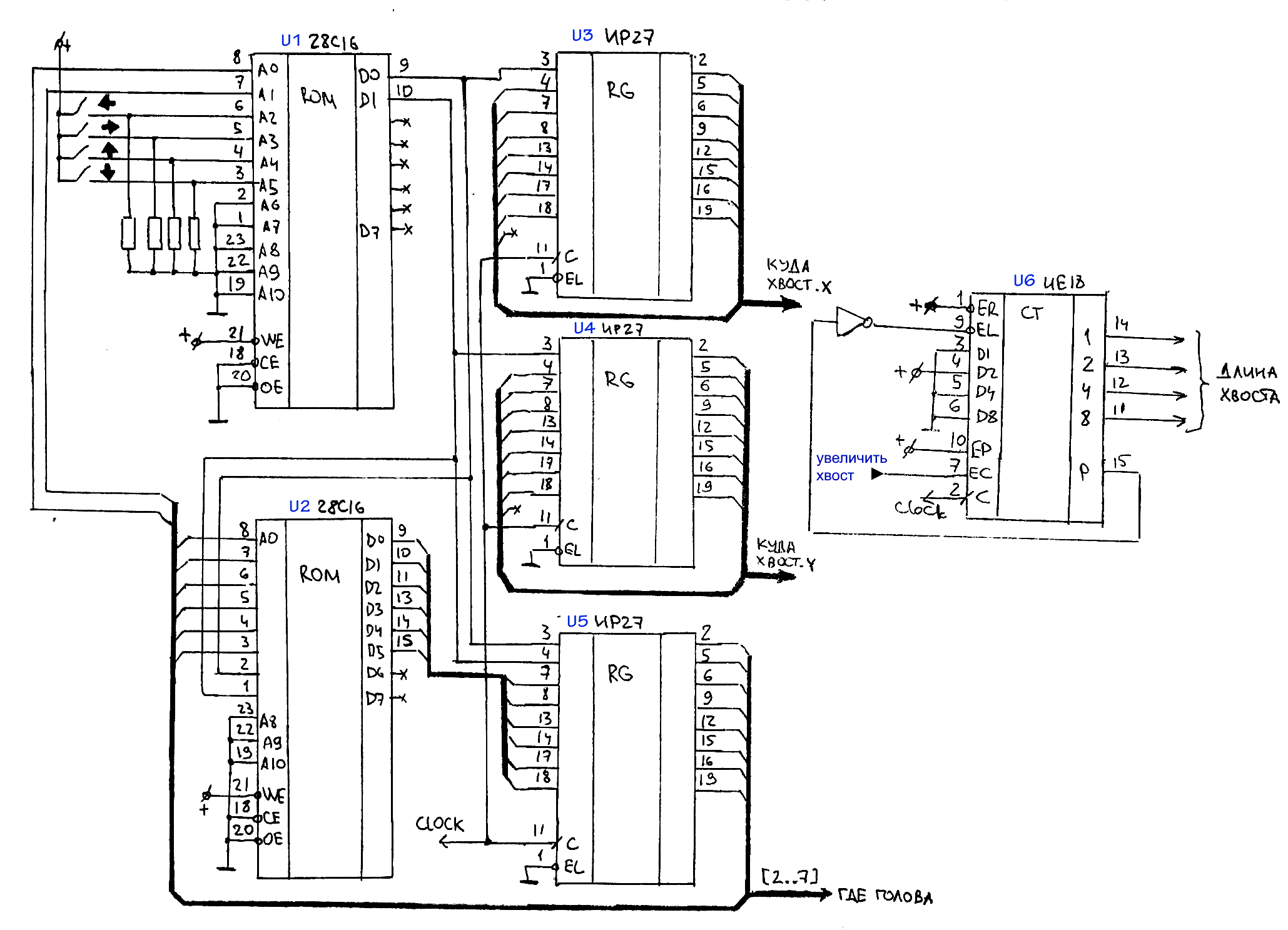
Subtotal
I hope that this article has interested you and I will try to quickly finish the second part.And if you are already torn into battle, stocked up with breadboards, microcircuits and dot screens, then a file with the ROM circuit and firmware is attached to this article. Mini-spoiler: to repeat the design you will need about 6 prototypes, 4 EEPROM 28C16 and a little more than two dozen other chips.Well, as it should be: like, share, retweets, sign up, press the bell, etc. ...)) And for today everything, thanks for your attention! To be continued…
Archive with ROM firmware and the generalUPD scheme : the second part is available here .