The project was built on the basis of another well-known project in its circles - linorobot (linorobot.org), using components available to a simple layman. The goals that were set: to achieve autonomous movement of the robot at home using low-cost components, to evaluate the performance of mini-PCs for the stated purposes, to configure the navigation stack to move in the narrow spaces of the Khrushchev.Iron
The list of components in the solids is as follows:- raspberry pi 3b - 2800 r.;
- lidar rplidar a1 - 7500 p.;
- power bridges l298n -2pcs - 400 rub .;
- wheelset with encoders of type A and B - 2000 r. (210 rpm - link )
- teenzy 3.2 - 2100 r .;
- imu 9250 (either 9150 or 6050) - 240 p.;
- power bank at 10000mH - 1500 r.
- 3 batteries 18650 and holder -600 p.
- step-down converter dc-dc c 5V to 3.3V - 20p.
- a piece of plywood, parquet -? rub.
Total: 17160 p.* The cost can be reduced by replacing teenzy with arduino mega 2560 (600 p.), And lidar by replacing kinect v.1 (1000 p.):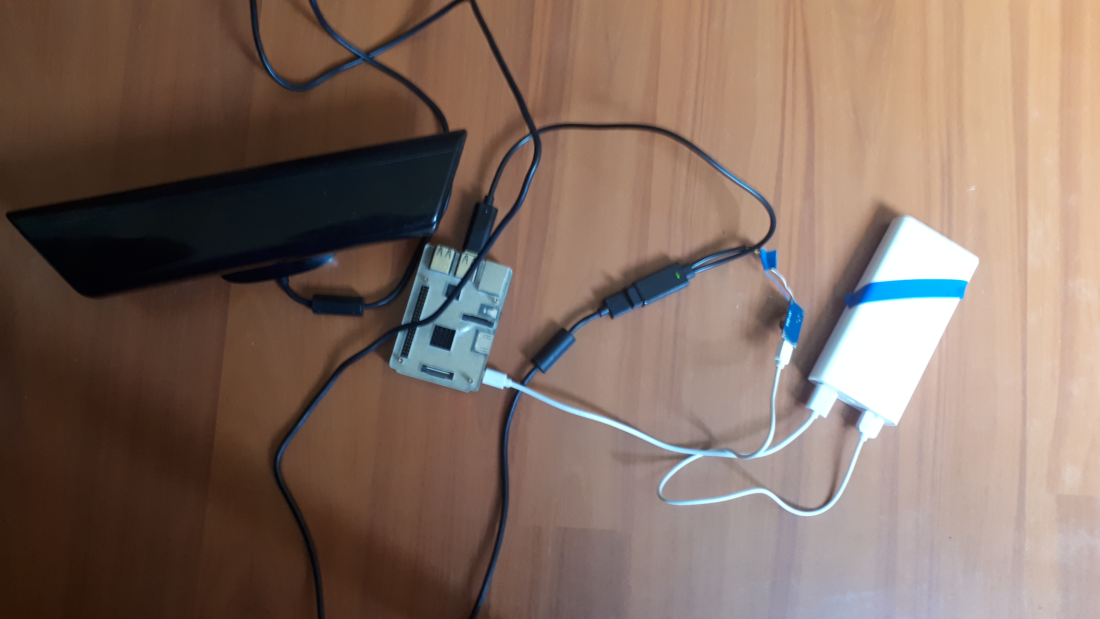 However, it should be noted that the first kinect has a minimum visibility (blind area) of 0.5 m, which can negatively affect navigation in cramped conditions and it is rather bulky. The lidar has a blind zone of less than 0.2 m. Kinect v.2 will not fit raspberry 3b (it does not have usb 3.0). Arduino mega is inferior to teenzy in size (and some characteristics), in addition, you will have to slightly rework the code.In general, the “design” looks like this:
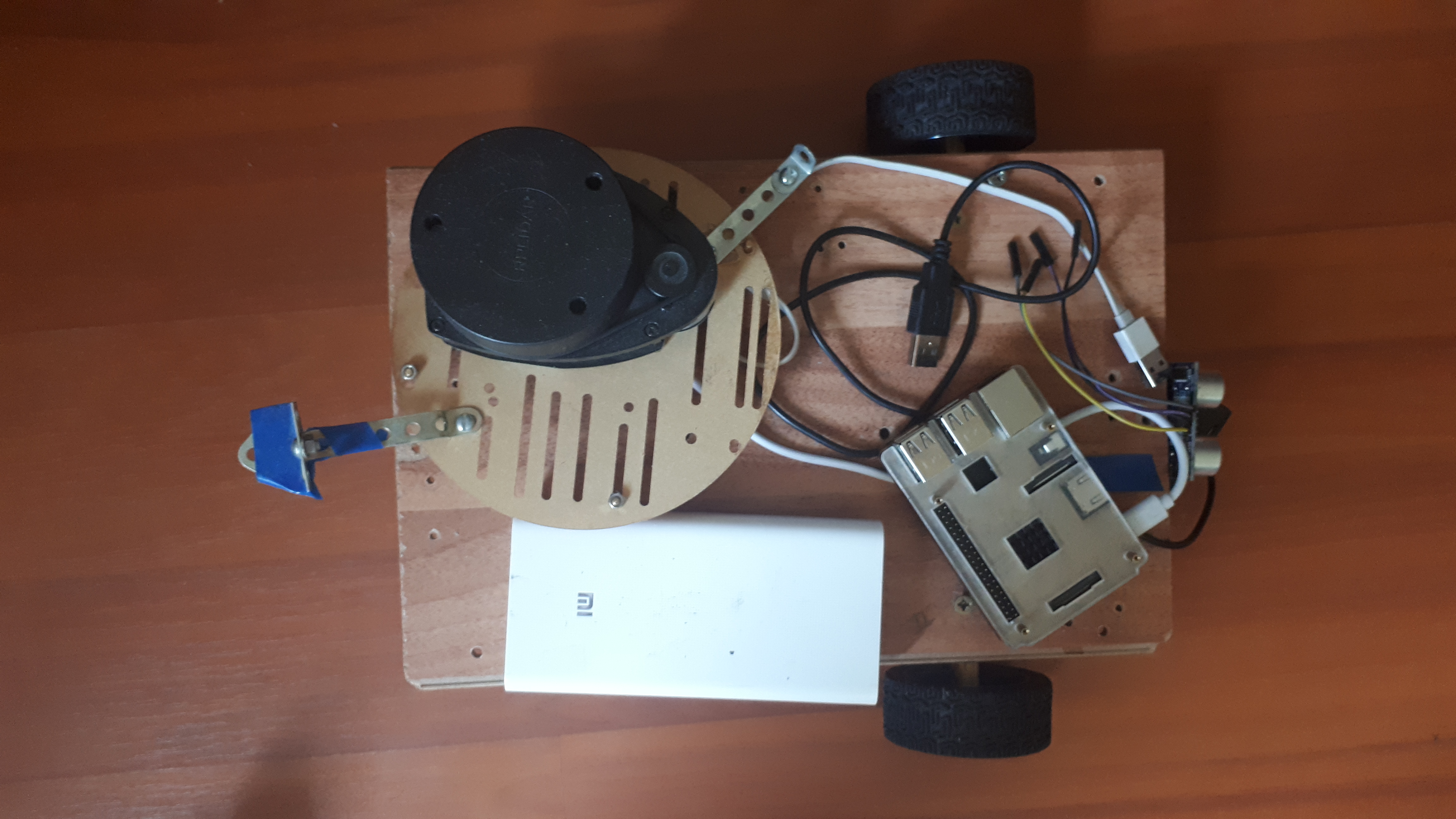
 There is no beauty here, of course, but this is not about it.In addition to the robot itself, it is highly desirable to have an external PC on which graphical shells for visualizing the actions of the robot (rviz, gazebo) will be launched.
Robot assembly
It is painted in detail on the project website - a link , so let us dwell on the points that cause difficulties. First you need to consider that the encoders on the wheelset are powered by 3.3V and, when 5V is applied, fail perfectly.The linorobot installation script is successfully installed on ubuntu 16.04, ubuntu 18.04. ROS versions: ROS kinetic or ROS melodic. On raspberry 3b, you must first create a swap file.The main teenzy code is along the way:roscd linorobot/teensy/firmware/lib/config
nano lino_base_config.h
And poured into it with the command:roscd linorobot/teensy/firmware
platformio run --target upload
The above bundles of commands will be used quite often, so it makes sense to add them to aliases.Because of the difficulties in assembling the robot, the correct correlation of connected contacts going from l298n to teenzy can be troublesome. Despite the extremely clear connection diagram, the wheels can behave differently and have to experiment, choosing the correct pin assignment in the code.In my case, it turned out like this:/// ENCODER PINS
//MOTOR PINS
The second point is to prescribe the specification of the robot wheels://define your robot' specs here
#define MAX_RPM 210 // motor's maximum RPM
RPM can be found in the wheel specification, but CPR (COUNTS_PER_REV) is the calculated value.CPR = PPR x 4. PPR of our wheels 341.* PPR can either be viewed in the specification or run the code on the roslaunch linorobot minimal.launch robot and spin the wheel 360 degrees. PPR will be equal to the numerical value that will be displayed on the screen after wheel rotation: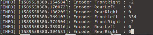 * PPR = abs (RECENT_COUNT - INITIAL_COUNT).So CPR = 1364. You also need to set WHEEL_DIAMETER and LR_WHEELS_DISTANCE in meters. Moreover, LR_WHEELS_DISTANCE is the distance between the central axles of the wheels, and not from edge to edge. Other indicators can be ignored if the robot is two-wheeled, differential (not omni).The third point that can cause difficulties - imu calibration. To do this, following the instructions, it is necessary to fix the robot in certain positions. The hints will be in the code when executing the rosrun imu_calib do_calib script :
 after completion imu_calib.yaml with settings will be generated.It is better to perform calibration, despite the fact that there is a default file with imu settings.* In addition, it turned out that imu calibration can affect the direction of movement of the robot through teleop (left instead of right and vice versa, while the movement back and forth was correct). The situation was not solved by rearrangement of pins in the code. Imu itself was fixed and calibrated with upside down brackets, as fixed on the back of the robot base. His (imu) further flip without recalibration solved the problem.Fourth point - pid calibration.On the project website, the procedure for how to implement the adjustment is described in detail - link .However, it will be difficult for a beginner to figure out what it is and how to work with it. In general, pid regulation is needed to ensure that the robot moves uniformly, without jerking / sudden braking. Three parameters are responsible for this: p, i, d. Their values are contained in the main code uploaded to teenzy:
You can experiment with them by running on the robot:roslaunch linorobot minimal.launch
Further on the external PC in three different terminals:rosrun lino_pid pid_configure
rosrun teleop_twist_keyboard teleop_twist_keyboard.py
rqt
By moving the sliders p, d, i in the rqt terminal, and then controlling the robot in the teleop_twist_keyboard terminal, you can achieve the necessary results without having to download the code with the new pid parameters each time in teenzy: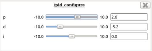 That is, everything happens on the fly and at that time in the firmware teenzy may have completely different meanings. * You can not focus on charts, because visually, and so it will be understood HOW the robot is traveling.They recommend starting with setting the values p = 1.0, d = 0.1, i = 0.1. In our case, the values are as follows (obtained experimentally) p = 2.0, i = 0.3, d = 0.1.Next, these values must be set in the code and filled in teenzy.Also, do not forget to set in the code (DEBUG 0 instead of DEBUG 1):
Odometry
For orientation of the robot and subsequent navigation, lidar data, imu and wheel encoder data are used. If imu calibration is performed correctly, the lidar is correctly installed, and the encoder values are correct, then there should be no problems with odometry.To check the correctness of odometry, you need to ride a bit on the robot via teleop and see the values in the odom topic, this is written on the project page - link .And also look into the visual shell of rviz: One cell in rviz is 1 m, so it is advisable for the robot to pass this meter both in the visual editor and also in kind.In addition, the distance traveled is displayed in the indicator w:
 It should also tend to 1 m.The same applies to the rotation angles of the robot:
 * In rviz and live, the robot must rotate at the same angles.Odometry from a lidar is defined in a similar way - a link. The distance from the lidar to the nearest wall both live and in rviz should match.
TF
In ROS, special attention is given to transformations - tf. In general terms, this concept describes the correlation of objects relative to each other in space. So that objects do not hang in the air, and the program understands how they are presented relative to each other, it is necessary to pay attention to the tf setting.In the project, all tf connections are already configured relative to each other and you only need to adjust the indicators, for example, indicate how the lidar is located. This is necessary for the robot to understand that the obstacle did not arise directly in front of him, but in front of the lidar, which is separated from the center of the robot at a certain distance.Let's go to the appropriate directory:roscd linorobot/launch
nano bringup.launch
The base itself is located at a distance of 0.065 m from the floor:<node pkg="tf_ros" type="static_transform_publisher" name="base_footprint_to_base_link" args="0 0 0.065 0 0 0 /base_footprint /base_link "/>
In laser.launch, you need to set the location of the lidar relative to the center of the robot base:roscd linorobot/launch/include
nano laser.launch
In my case, the lidar is shifted along the x axis: -0.08, y: 0.04 and "rises" above the base (z axis): 0.08m:<node pkg="tf2_ros" type="static_transform_publisher" name="base_link_to_laser"
args="-0.08 0.04 0.08 0 0 0 /base_link /laser "/>
In rviz, this location can be observed visually: While not far from the lidar, we’ll adjust its frequency so that it gives out more points (by default it gives 4k), this will help in building the map:
cd linorobot/launch/include/lidar
nano rplidar.launch
Add parameter:<param name="scan_mode" type="string" value="Boost"/>
and change<param name="angle_compensate" type="bool" value="false"/>
Now 8k is at our disposal: The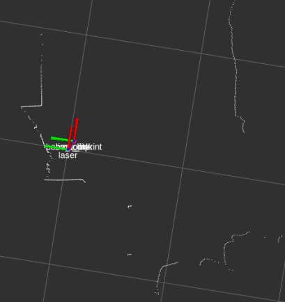 physical location of the lidar on the robot also matters:
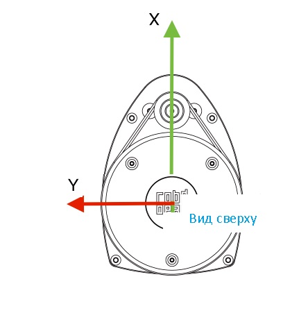
Building a 2d room map
On the project website it is proposed to build a room map by launching in two terminals:roslaunch linorobot bringup.launch
roslaunch linorobot slam.launch
However, practice has shown that slam, which comes by default with the project, refuses to work when the lidar mode is 8k: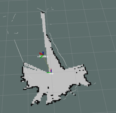 while in 4k mode, the cards are not very successful, they are very noisy.Therefore, it is better to use another slam - hector-slam.How to install it is indicated here .After installation, the procedure for creating a map will be the same, but instead of roslaunch linorobot slam.launch, run roslaunch my_hector_mapping my_launch.launchMaps are cleaner, but then they are better to modify in a graphical editor, removing unnecessary ones, especially if the lidar collided with mirrors when building the map :
 Do not forget to save the room map:
rosrun map_server map_saver -f my-map
* Maps are better obtained in a pleasant twilight, this will squeeze the most out of the budget lidar.To be continued.