Hello, Habr!In this article I would like to talk about my experience connecting LCD displays to the STM32 microcontroller using the HAL library on the I2C bus.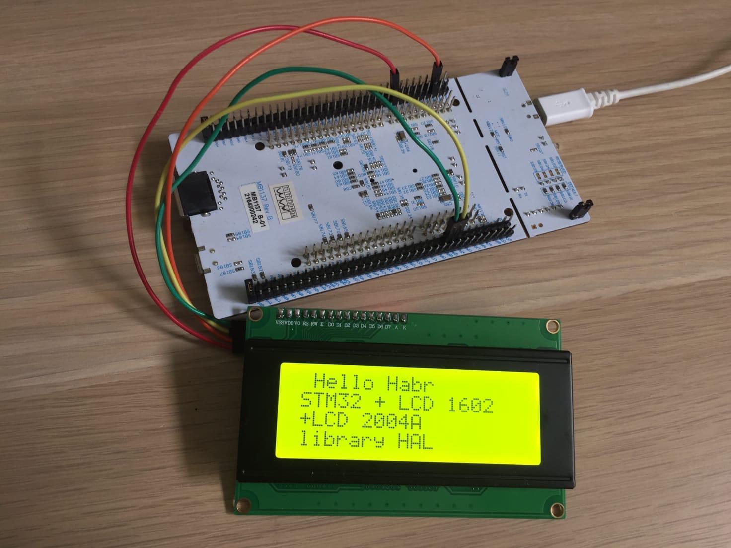 I will connect the display 1602 and 2004. They both have a soldered I2C adapter based on the PCF8574T chip. The debug board will be Nucleo767ZI , and the development environment will be STM32CubeIDE 1.3.0.I will not talk in detail about the principle of operation of the I2C bus, I advise you to look here and here .We create the project, select the debug board: We
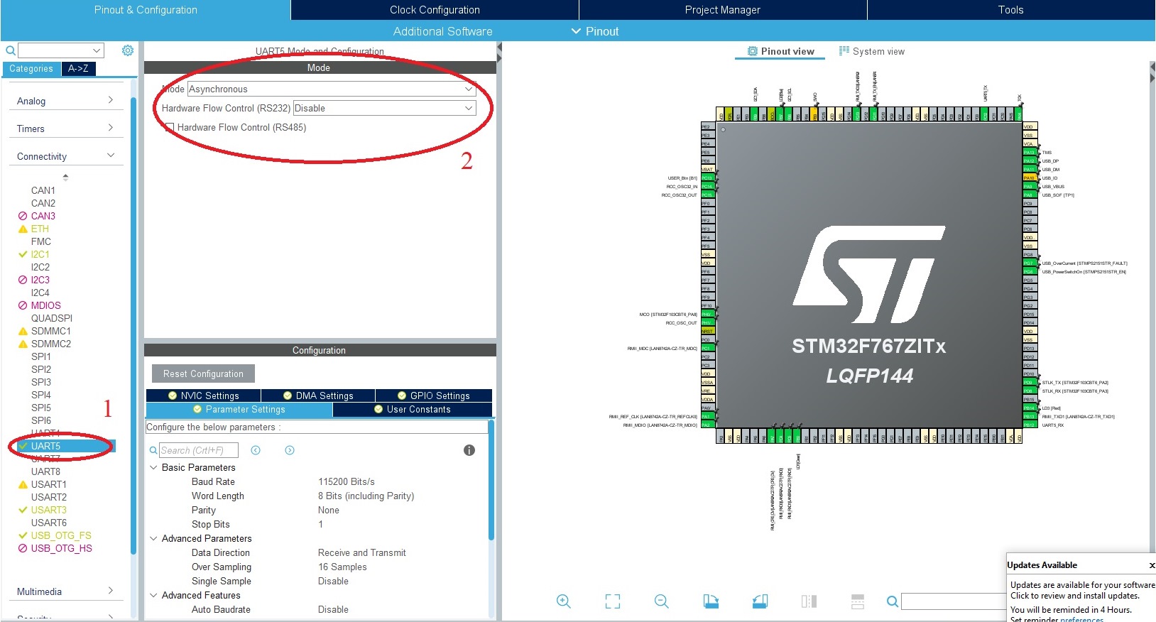
 indicate that we will use I2C1. I will also connect UART5 to communicate with the board, this is necessary to receive information from the board about the display address.
 In the same window, you can see the numbers of the legs to which the display is connected, in my case it turned out like this:
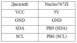 To start, connect only one display, I will start with 1602. Also, I will connect the USB-UART CH340 adapter, known to experienced arduin drivers, to receive data from the board.
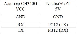 Please note that the adapter connects RX to TX and TX to RX, the jumper on the adapter is 3.3V
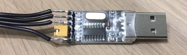 Let's take a closer look at working with the PCF8574T chip and display. Below is a schematic diagram of a module with a display:
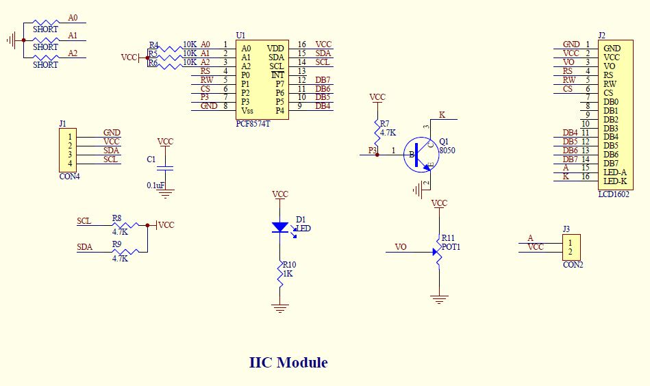 The PCF8574T chip is similar in functionality to the shift register 74hc595 - it receives bytes via the I2C interface and assigns the values of the corresponding bit to its outputs (P0-P7).Consider which pins of the microcircuit are connected to the display and what they are responsible for:
- The terminal P0 of the microcircuit is connected to the RS terminal of the display, which is responsible for receiving the display data (1) or display operation instructions (0);
- Pin P1 is connected to R \ W, if 1 - write data to the display, 0 - read;
- Terminal P2 is connected to CS - the terminal, upon the change of state of which is being read;
- Conclusion P3 - backlight control;
- Conclusions P4 - P7 are used to transmit data to the display.
Several devices can be connected to one I2C bus at the same time. In order to be able to access a specific device, each of them has its own address, first we will find out. If the contacts A1, A2 and A3 on the adapter board are not sealed, then the address will most likely be 0x27, but it is better to check. To do this, we will write a small function that will show the addresses of all devices that are connected to the I2C bus:void I2C_Scan ()
{
HAL_StatusTypeDef res;
char info[] = "Scanning I2C bus...\r\n";
HAL_UART_Transmit(&huart5, (uint8_t*)info, strlen(info), HAL_MAX_DELAY);
for(uint16_t i = 0; i < 128; i++)
{
res = HAL_I2C_IsDeviceReady(&hi2c1, i << 1, 1, HAL_MAX_DELAY);
if(res == HAL_OK)
{
char msg[64];
snprintf(msg, sizeof(msg), "0x%02X", i);
HAL_UART_Transmit(&huart5, (uint8_t*)msg, strlen(msg), HAL_MAX_DELAY);
HAL_UART_Transmit(&huart5, (uint8_t*)"\r\n", 2, HAL_MAX_DELAY);
}
else HAL_UART_Transmit(&huart5, (uint8_t*)".", 1, HAL_MAX_DELAY);
}
HAL_UART_Transmit(&huart5, (uint8_t*)"\r\n", 2, HAL_MAX_DELAY);
}
This function polls all addresses from 0 to 127 and if a response is received from this address, it sends the address number in hexadecimal form to UART.To communicate with the board, I use the Termite program. By default, the UART speed of the microcontroller is set to 115200, you must set the same in termite. We call the function in the main body of the program, flash the board and connect in termite to our microcontroller: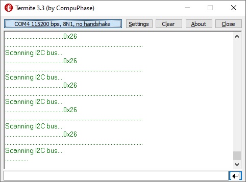 Dots show all the addresses from which the answer was not received. The address on my display is 0x26, since I soldered the jumper A0. Now connect the second display parallel to the first, and see what the program will give:
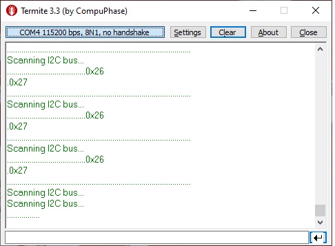 We have two addresses: 0x26 (display 1602) and 0x27 (display 2004). Now about how to work with the display. The microcontroller sends an address byte, and all devices connected to the bus check it with their own. If it matches, then the module starts communication with the microcontroller. First of all, you need to configure the display: where the character count will go from and in which direction, how the cursor will behave, etc. After that, it will already be possible to transmit information for display to the display. The peculiarity is that we can use only 4 bits to transmit information, i.e. data must be broken into two parts. The data is stored in the high bits (4-7), and the low bits are used to indicate whether the backlight will turn on (3 bits), whether data is coming for output, or display settings (RS output, 0 bits), and 2 bits, by the change of which the reading takes place, i.e.e to send 1 byte of data you need to send 4 bytes - the 1st byte will contain 4 bits of information, the 2nd bit to state 1, the 2nd byte is a repetition of the 1st, only the 2nd bit to state 0. The 3rd and 4th bytes are similar, only they contain second half of the data. It sounds a little incomprehensible, I'll show you an example:
void I2C_send(uint8_t data, uint8_t flags)
{
HAL_StatusTypeDef res;
for(;;) {
res = HAL_I2C_IsDeviceReady(&hi2c1, LCD_ADDR, 1, HAL_MAX_DELAY);
if(res == HAL_OK) break;
}
uint8_t up = data & 0xF0;
uint8_t lo = (data << 4) & 0xF0;
uint8_t data_arr[4];
data_arr[0] = up|flags|BACKLIGHT|PIN_EN;
data_arr[1] = up|flags|BACKLIGHT;
data_arr[2] = lo|flags|BACKLIGHT|PIN_EN;
data_arr[3] = lo|flags|BACKLIGHT;
HAL_I2C_Master_Transmit(&hi2c1, LCD_ADDR, data_arr, sizeof(data_arr), HAL_MAX_DELAY);
HAL_Delay(LCD_DELAY_MS);
}
Let's take it in order. In the beginning there are variables that store the display address, and bits of settings that must be sent each time along with the data. In the sending function, we first of all check whether there is a module at the recorded address. In case of receiving the HAL_OK message, we begin to form bytes for sending. At the beginning of the byte that we will send, it is necessary to divide into two parts, write both of them to the high bits. Suppose we want the display to display the character 's', in the binary system it is 1110011 ( calculator) Using the logical operation & we write up = 01110000 into the variable, i.e. write only the most significant bits. The low-order bits are shifted to the left by 4 characters at the beginning, and then are written into the variable lo = 00110000. Next, we form an array of 4 bytes that contain information about the character to be displayed. Now we assign configuration bits (0-3 bits) to existing bytes. After that, we send the address byte and 4 bytes of information to the display using the HAL_I2C_Master_Transmit () function;But do not rush to download the program, because in the beginning you need to set the display settings. The site has an excellent translated table with commands for customizing the display. Having checked it with the documentation, I came to the following settings that are optimal for myself: I2C_send(0b00110000,0);
I2C_send(0b00000010,0);
I2C_send(0b00001100,0);
I2C_send(0b00000001,0);
We place these commands before the beginning of an infinite loop, so that the settings are sent once before starting work (like the void setup in arduinki). The I2C_send function, in addition to the byte, requires you to specify whether display settings or data will be sent. If the second argument of the function is 0, then the settings, and if 1, then the data.And the last touch - you need a function that will send a deadline character-by-character. Everything is pretty simple here:void LCD_SendString(char *str)
{
while(*str)
{
I2C_send((uint8_t)(*str), 1);
str++;
}
}
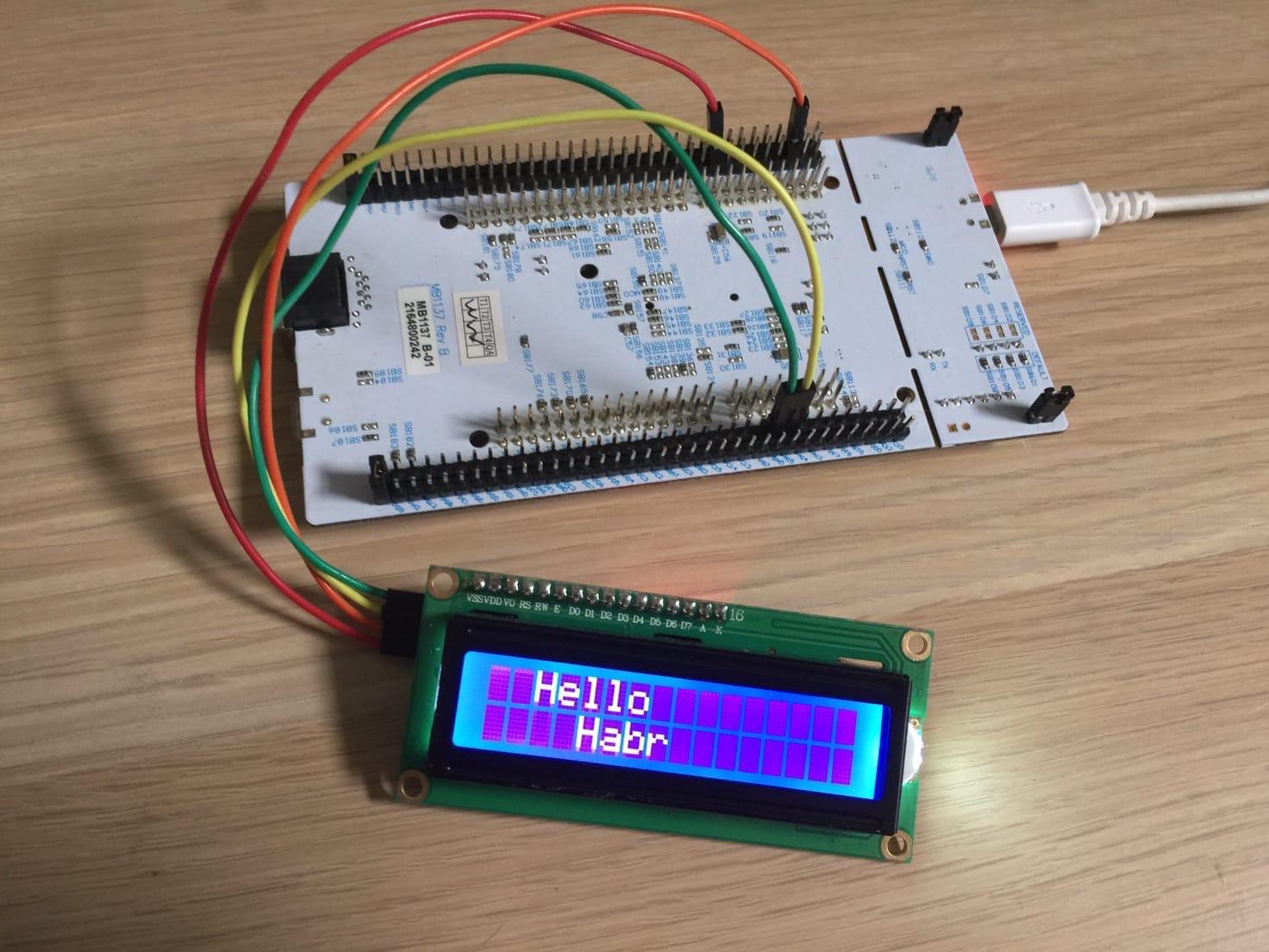
Having collected all these functions together, you can write: LCD_SendString(" Hello");
I2C_send(0b11000000,0);
LCD_SendString(" Habr");
 Well, we figured out the 1602 display, now 2004. The difference between them is minimal, even this code will work fine. All the difference comes down to organizing the addresses of the cells on the display. In both displays, the memory contains 80 cells, in the 1602 display, the first 16 cells are responsible for the first line, and cells 40 to 56 are responsible for the second line. The remaining memory cells are not displayed, so if you send 17 characters to the display, the last one will not be transferred on the second line, and will be recorded in a memory cell that does not have an output to the display. A little more clearly, the memory is organized as follows:
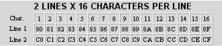 To use the line feed, I used the I2C_send command (0b11000000,0); , it just goes to 40 cell. The 2004 display is more interesting.The first row is cells 1 to 20The second row is cells 40 to 60The third row - cells from 21 to 40The fourth row - cells from 60 to 80,i.e. if you send a command
LCD_SendString("___________________1___________________2___________________3___________________4");
We get the following: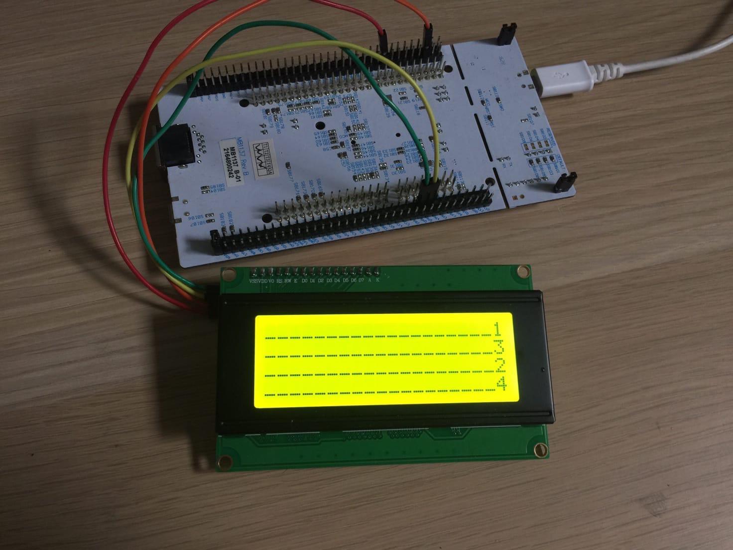 To organize transitions between lines, you must manually move the cursor to the desired memory cell, or you can programmatically supplement the function. I have so far settled on the manual version:
 I2C_send(0b10000000,0);
LCD_SendString(" Hello Habr");
I2C_send(0b11000000,0);
LCD_SendString(" STM32 + LCD 1602");
I2C_send(0b10010100,0);
LCD_SendString(" +LCD 2004A");
I2C_send(0b11010100,0);
LCD_SendString(" library HAL");
Result:That's probably all with these displays, useful links thanks to which I was able to figure it all out:- The code looked a lot here
- Tables for display configuration looked here
- The procedure was looked here
Program and datasheetPS: do not forget to adjust the brightness of the display in advance.