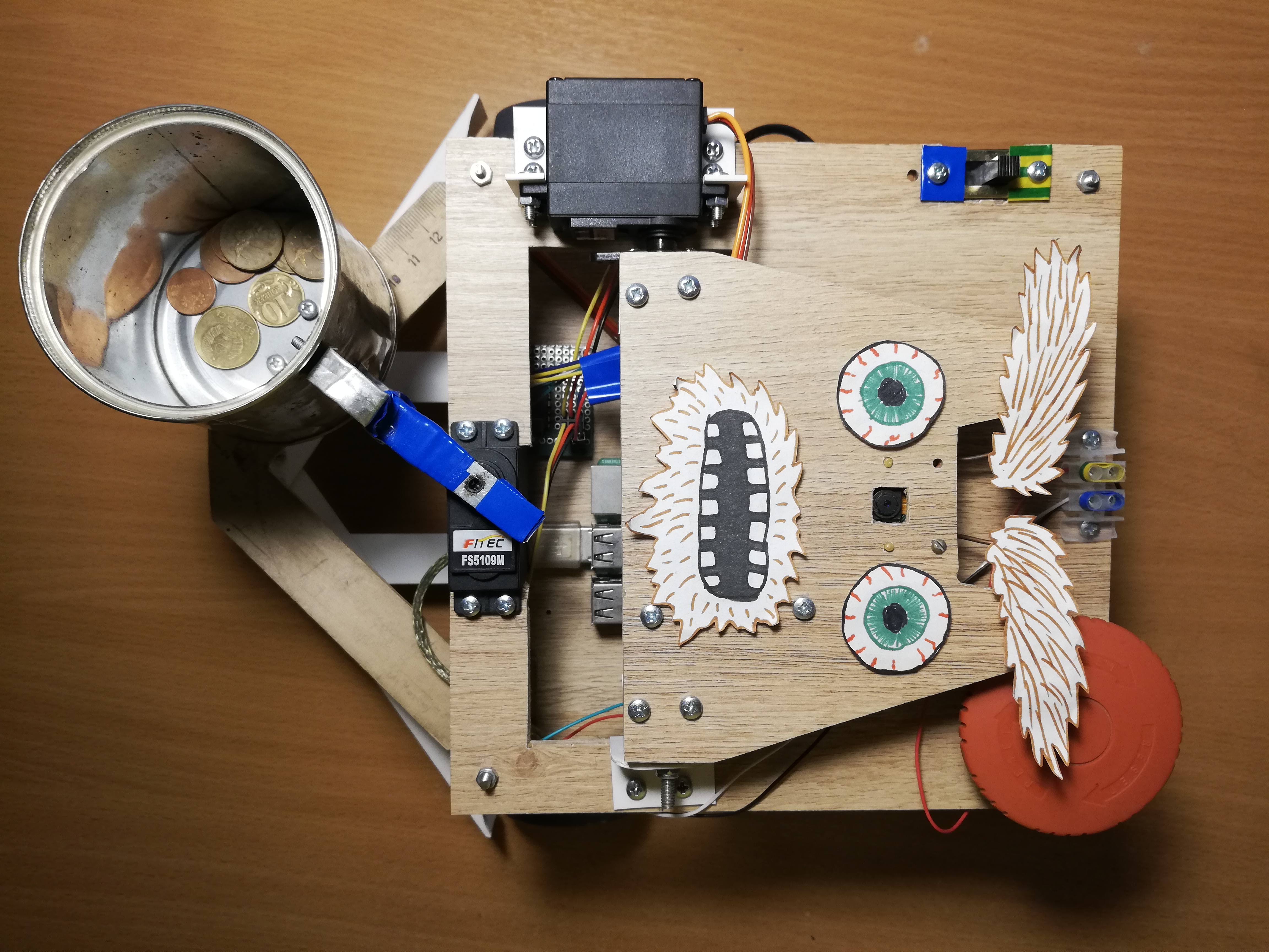
Usually, two such questions arise for such crafts: “how?” and for what?" The publication itself is devoted to the first question, and I will answer immediately to the second:I started this project in order to master robotics, starting with the Raspberry Pi and the camera. As you know, one of the best ways to learn something is to come up with a technical task and try to fulfill it, while getting the necessary skills.At that time, I still had no bright ideas in the field of robotics, so I decided to make an exclusively fun project - a beggar robot. The result is a standalone robot on the Raspberry Pi and ROS, using the Movidius Neural Cumpute Stick to detect faces. He wanders around the room, looking for people, and shakes a can in front of them. Here's what this robot looks like: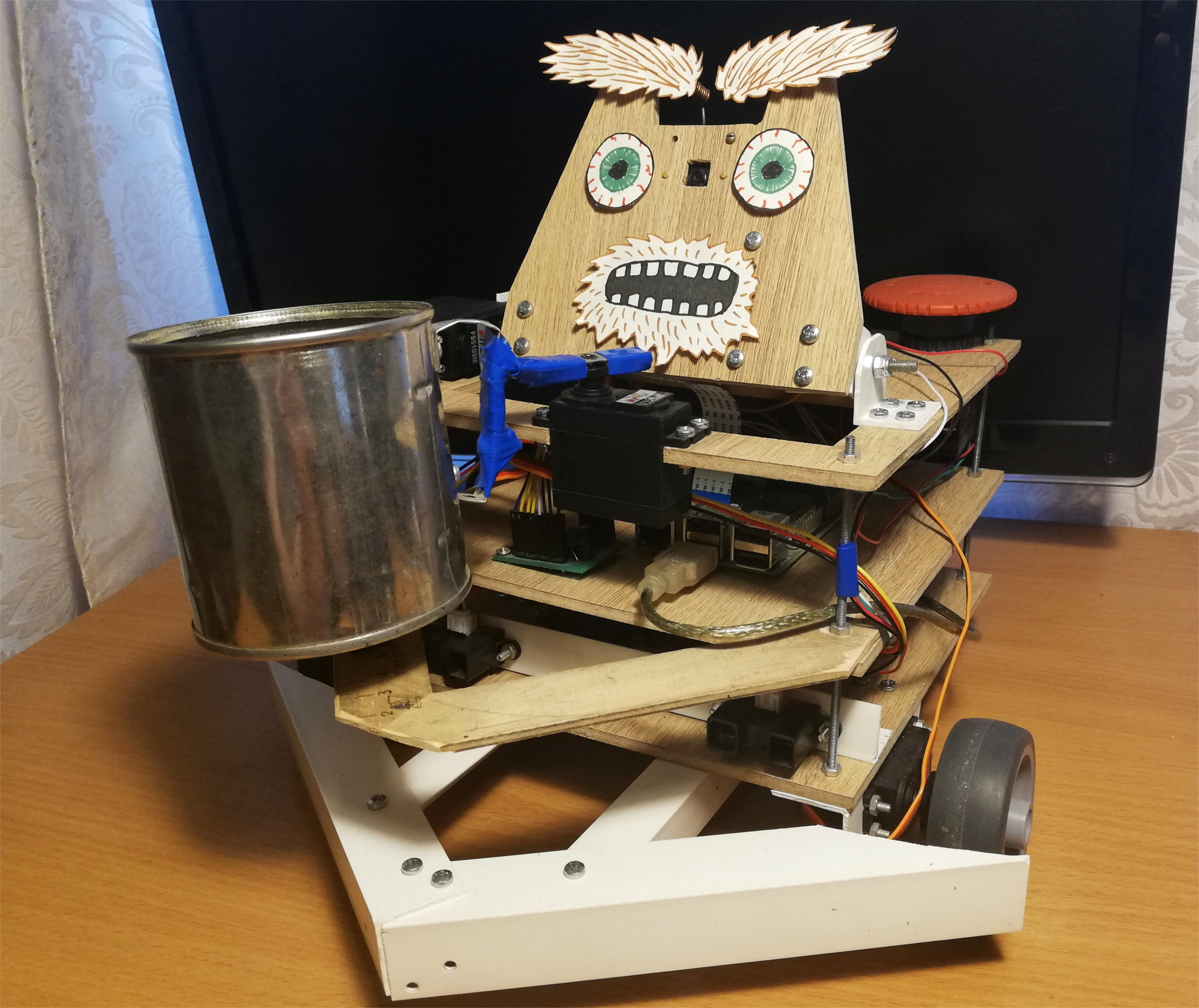 The robot randomly moves around the room, and if it notices a person, it rolls up to it and shakes a jar for small things. For fun, I added a little facial expression to him - he knows how to move his eyebrows:
 After the first attempt, the robot tries to find his face again in sight, turns to the person and shakes the bank again. But what happens if you leave at this moment:
Robot
I took the idea of a begging robot from the magazine Popular Mechanics . The prototype authorship of Chris Eckert called Gimme looks very aesthetically pleasing.I wanted to concentrate more on functionality, so the case was assembled from improvised materials. In particular, PVC corners proved to be the most versatile material with which you can connect almost any two parts. It seems that at the moment the robot is five percent composed of PVC corners and M3 screws. The case itself consists of three laminate platforms on which the head and all the electronics are mounted.The basis of the robot is Raspberry Pi 2B , and the code is written in C ++ and lies on GitHub .Vision
To perceive reality, the robot uses the Paspberry Pi Camera Module v2 camera , which can be controlled using the RaspiCam library .For face detection, I tried several different approaches. The quality of classic detectors from OpenCV did not satisfy me, so in the end I came to a rather non-standard solution. Detection of persons engaged in the neural network, running on the device Movidius Neural Compute Stick (NCS) under the control framework OpenVINO .NCS is such a piece of hardware for the effective launch of neural networks, inside of which there are several vector processors specially tailored for this. The device is connected via USB and consumes only 1 Watt of power. Thus, the NCS acts as a co-processor for the Raspberry Pi, which does not pull the neural network. While the NCS is processing the next frame, the Paspberry processor is free for other operations. It is worth noting that for optimal operation of the device, a USB 3.0 interface is required, which is not available on older versions of Raspberry; with USB 2.0 it also works, just slower. Also, in order not to block the Raspberry USB connectors, I connect the NCS to it via a short USB cable. I wrote in detail about working with the Neural Compute Stick in my previous article .At first I tried to trainown face detector with MobileNet + SSD architecture on open datasets. The detector really worked, but not very stable: with the inevitable deterioration of the shooting conditions (exposure and blurry shots), the quality of the detector sagged greatly. However, after some time, ready-made face detectors appeared in OpenVINO, and I switched to a detector with the SqueezeNet light + SSD architecture , which not only worked better in a variety of shooting conditions, but was also faster.Before uploading the image to the NCS to obtain the predictions of the detector, the image must be preprocessed. The detector of my choice works with color images , so the image must first be compressed. To do this, I use the lightest scaling algorithm - the nearest neighbor method (INTER_NEAREST in the OpenCV library). It works a little faster than interpolation methods, and almost does not affect the result. It is also worth paying attention to the order of the image channels: the detector expects the BGR order, so you need to set the same for the camera.I also tried to separate the video processing into two streams, one of which received the next frame from the camera and processed it, and the other at that time uploaded the previous frame to NCS and waited for the detector results. With this scheme, technically, the processing speed increases, but the delay between receiving the frame and receiving detections for it also increases. Because of this lagging behind reality, monitoring the face becomes only more difficult, so in the end I refused this scheme.In addition to actually detecting faces, they also need to be tracked to avoid detector errors. To do this, I use the lightweight tracker Simple Online Realtime Tracker (SORT) . This simple tracker consists of two parts: the Hungarian algorithm is used to match objects on adjacent frames, and to predict the trajectory of the object, if it suddenly disappears - Kalman filter . While I was playing with face tracking, I found that the trajectories predicted by the Kalman filter can be very implausible with sudden movements, which again only complicates the process.Therefore, I turned off the Kalman filter, leaving only the face matching algorithm and the counter of the sequential number of frames on which the face was detected - this way I get rid of the false positives of the detector.Upper platform, from left to right: camera, servos to control the head and eyebrows, switch, power terminals, Big Red Button.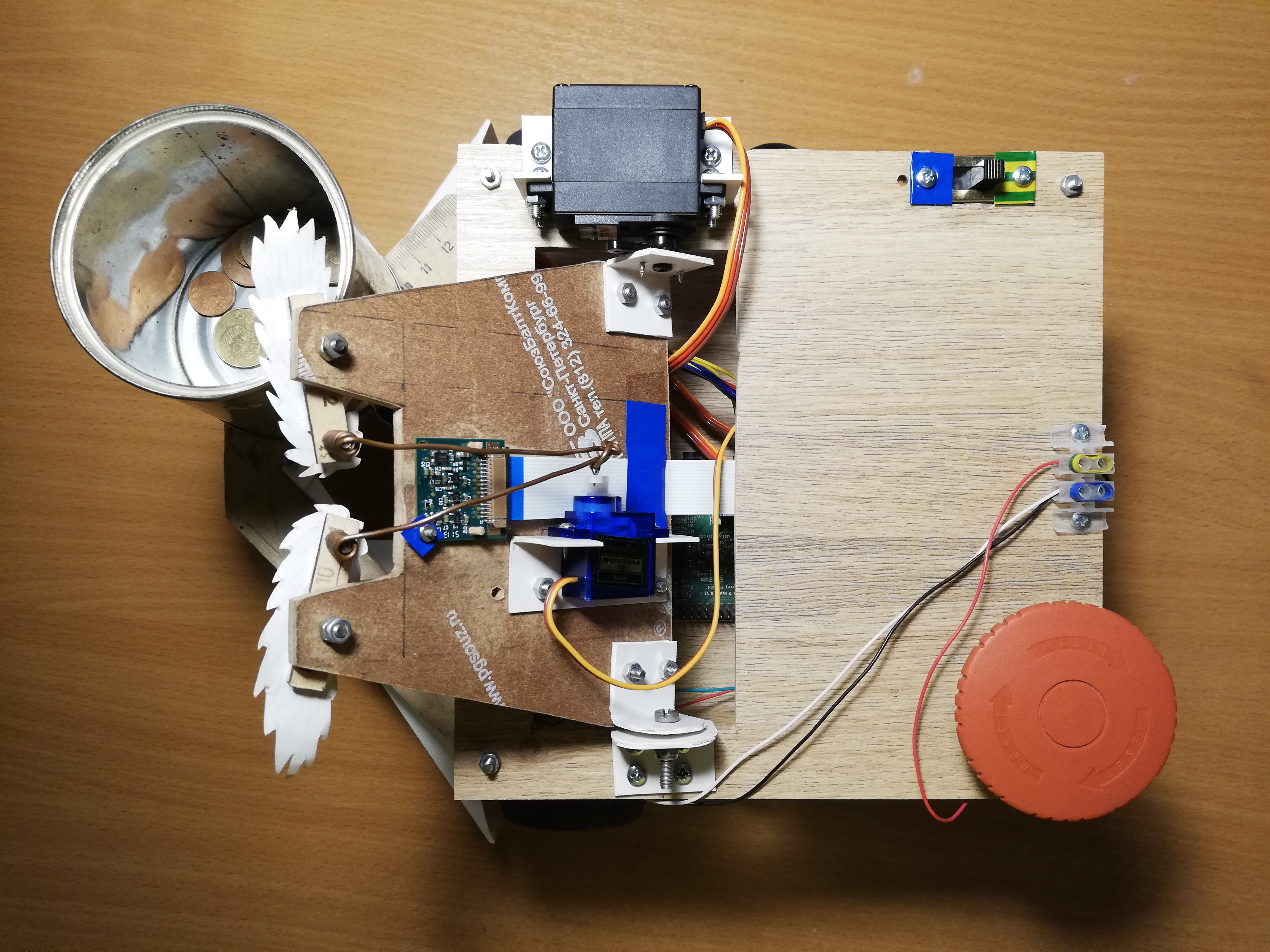
Traffic
For movement, the robot has five servos: two FS5103R continuous-rotation servos spin the wheels; There are two more ordinary FS5109Ms, one of which rotates the head, and the other shakes the can; finally, the little SG90 moves its eyebrows.To be honest, the SG90 mini-servos seemed like trash to me - one of my servos had the wrong control pulse width, and only one survived among the other four. In fairness, I accidentally took one of the servants with my elbow, but the other two simply could not bear the load (I used to use them for the head and the can). Even the last servo, which got the simplest job - moving the eyebrows, has to poke a stick from time to time so that it does not wedge. With other servos, I did not notice any problems. True, continuous rotation servos sometimes have to be calibrated so that they do not spin in the inactive state - for this there is a small regulator on them that can be turned with a clock-head screwdriver.Managing servos with Raspberry, it turns out, is not so simple. First, they are controlled bypulse-width modulation (PWM / PWM) , and on Raspberry there are only two pins on which PWM is supported by hardware . Secondly, of course, Raspberry will not be able to power the servos, it will not stand this. Fortunately, these problems are solved using an external PWM controller.Adafruit PCA9685 is a 16-channel PWM controller that can be controlled via the I2C interface . It is also very convenient that it has terminals for supplying power for servos. Moreover, [theoretically] it is possible to chain up to 62 controllers, while receiving up to 992 control pins - for this you need to assign a unique address to each controller using special jumpers. So if you suddenly need an army of servos - you know what to do.To control the PCA9685, there is a high-level library that acts as a WiringPi extension. Working with this thing is quite convenient - during initialization, it creates 16 virtual pins into which you can write a PWM signal, but first you have to calculate the number of ticks. To turn the servo lever to a certain angle in the range [0, 180], you must first translate this angle into the range of control pulse lengths in milliseconds [SERVO_MS_MIN, SERVO_MS_MAX]. For all my servos, these values are approximately 0.6 ms and 2.4 ms, respectively. In general, these values can be found in the servo datasheet, but practice has shown that they can differ, so they may need to be selected. Then divide the resulting value by 20 ms (the standard value of the length of the control cycle) and multiply by the maximum number of ticks PCA9685 (4096):void driveDegs(float angle, int pin) {
int ticks = (int) (PCA_MAX_PWM * (angle/180.0f*(SERVO_MS_MAX-SERVO_MS_MIN) + SERVO_MS_MIN) / 20.0f);
pwmWrite(pin, ticks);
}
Similarly, this is done with continuous rotation servos - instead of an angle, we set the speed in the range [-1,1].I assembled the robot chassis, as well as the body, from improvised means: I put furniture wheels on the servo-drives of continuous rotation, and a furniture ball support acts as the third wheel. Previously, instead of it, a wheel stood on a rotating support, but with such a chassis it was difficult to make precise turns, so I had to replace it. There is also a small wheel under the can to transfer part of the weight from the servo to the housing. A simple thing that was not obvious to me initially was that servo levers must be fixed with a screw, especially for wheels, so that they do not fall off along the way. Because of such stupidity, I had to redo the chassis once. I also made the robot a wide bumper made of PVC corners so that it doesn't get stuck so often.Now about what you can do about it. Firstly, you can shake the jar and move the eyebrows - for this you just need to turn the servo lever to pre-selected angles.Secondly, you can rotate your head. I didn’t want the head to spin at the maximum speed of the servo, because it has a camera on it. Therefore, I decided to programmatically reduce the speed: I need to turn the lever a small angle, then wait a few milliseconds - and so on until the desired angle is reached. In this case, it is necessary to remember the current absolute position of the head and each time check whether it has exceeded the permissible limits (on my robot it is in the range of [10, 90] degrees).Thirdly, you can change the direction of movement by changing the speed of rotation of the wheels. In the same way, you can rotate the platform, for example, to follow the face. The angular speed of rotation depends both on the servos themselves and on their location on the chassis, so it is easier to measure it once and then take it into account when cornering. To find the necessary delay between turning on the motors for rotation and turning them off, you need to divide the angle module by the angular velocity.Finally, you can rotate the head and chassis simultaneously and asynchronously so as not to waste time. I do it like this:auto waitRotation = std::async(std::launch::async, rotatePlatform, platformAngle);
success = driveHead(headAngle);
waitRotation.wait();
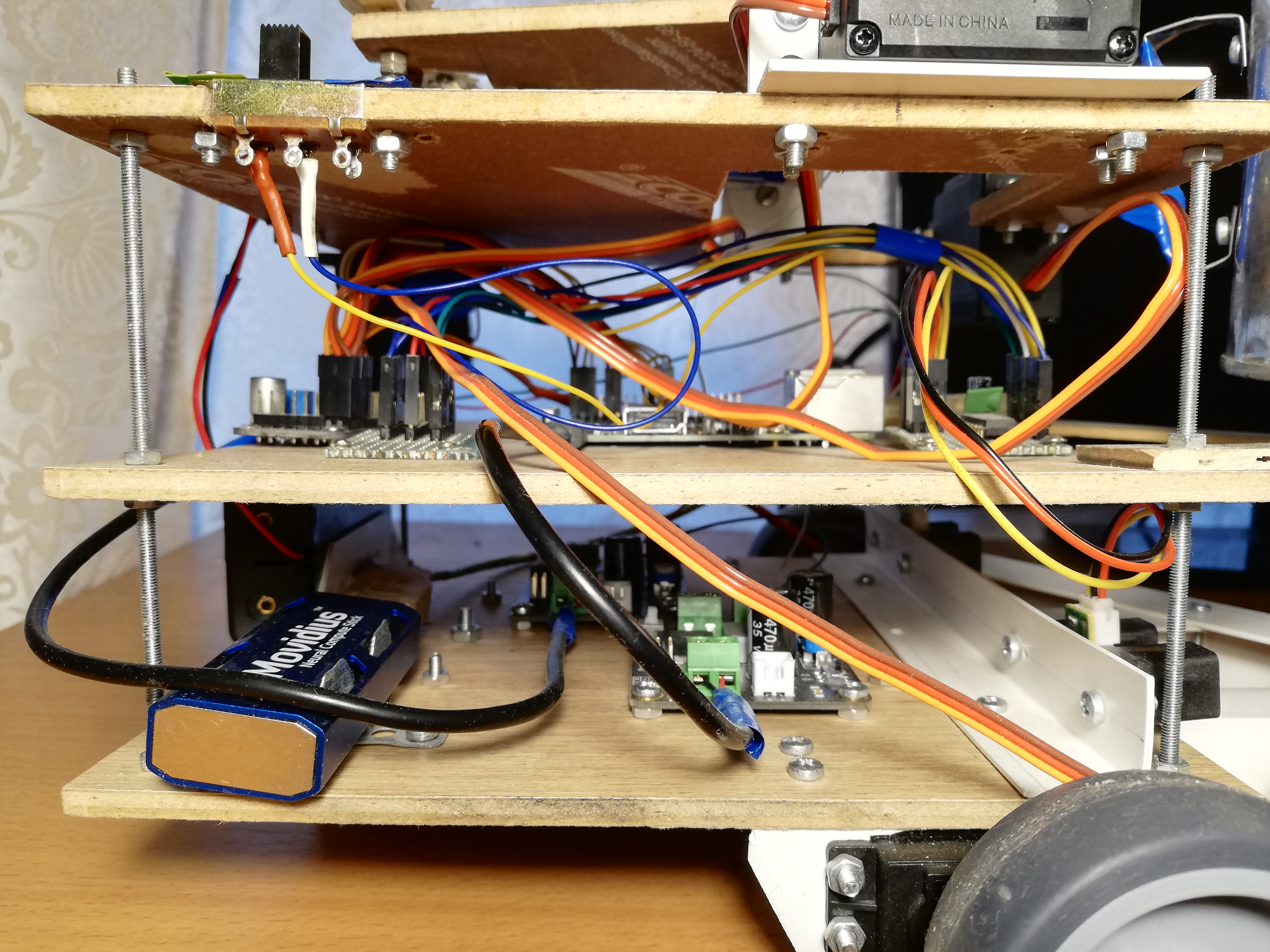
Central platform, from left to right: PCA9685, power bus, Raspberry Pi, MCP3008 ADC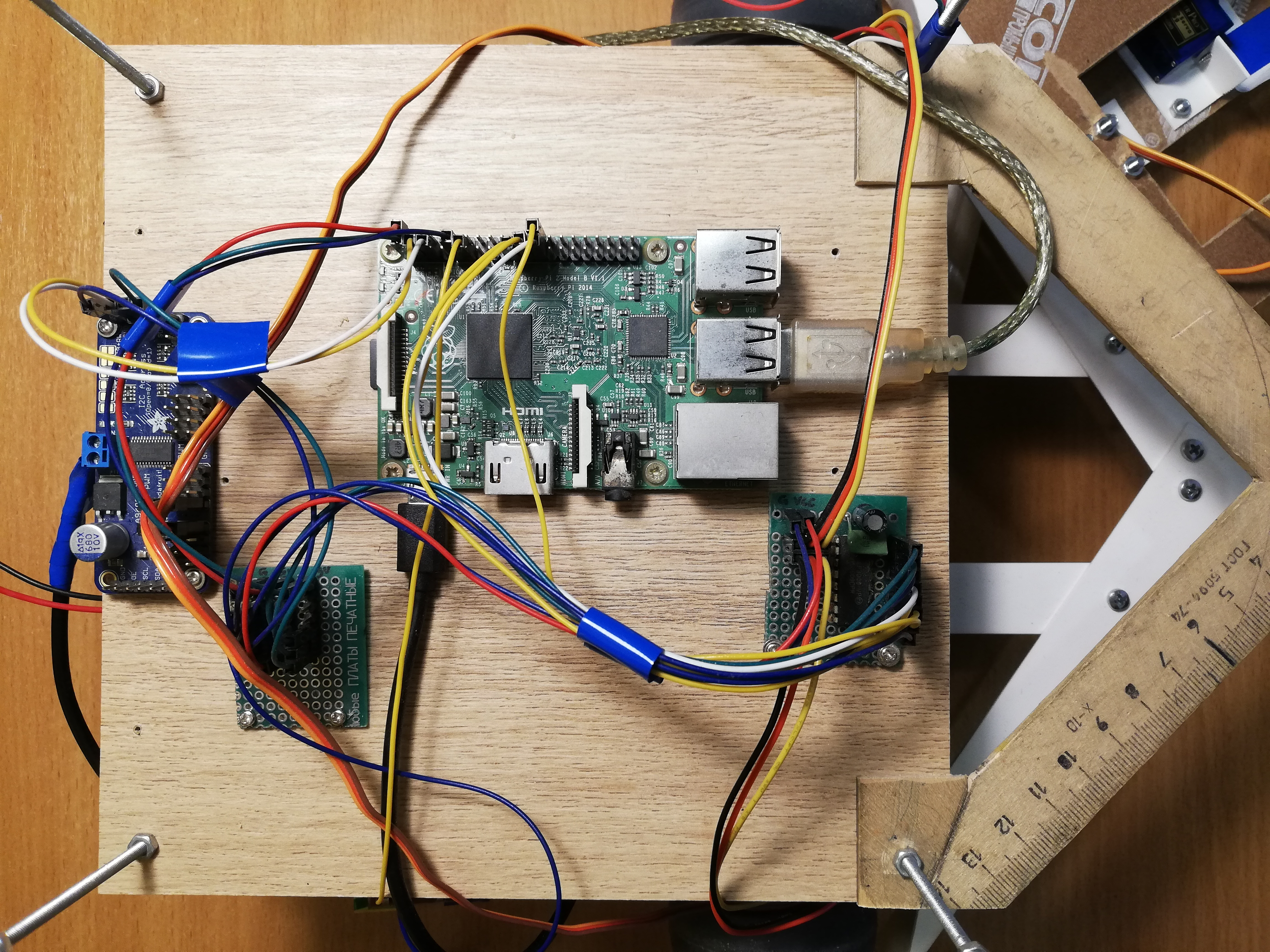
Navigation
Then I did not complicate anything, so the robot uses only two Sharp GP2Y0A02YK infrared range finders for navigation. This is also not so simple, because the sensors are analog, but Raspberry, unlike Arduino, has no analog inputs. This problem is solved by the analog-to-digital converter (ADC / ADC) - I use the 10-bit, 8-channel MCP3008. It is sold as a separate microcircuit, so it had to be soldered to a printed circuit board and pins were also soldered there to make it more convenient to connect. Also, on the advice of my bati, who fumbles more in circuitry, I soldered two capacitors (ceramic and electrolytic) between the legs of the power supply and the ground to absorb the noise from the digital part of the entire circuit. The sensors output no more than three volts at the output, so 3.3v with Raspberry can be connected as a reference ADC voltage (VREF) - the same as for the MCP3008 (VDD) power supply.The MCP3008 can be controlled via the SPI interface , and for this it’s even easy to find ready-made code on GitHub .Despite this, for convenient work with the ADC, you will need a few dances with a tambourine.unsigned int analogRead(mcp3008Spi &adc, unsigned char channel)
{
unsigned char spi_data[3];
unsigned int val = 0;
spi_data[0] = 1;
spi_data[1] = 0b10000000 | ( channel << 4);
spi_data[2] = 0;
adc.spiWriteRead(spi_data, sizeof(spi_data));
val = (spi_data[1]<< 8) & 0b1100000000;
val |= (spi_data[2] & 0xff);
return val;
}
Three bytes must be sent to the MCP3008, where the start bit is written in the first byte, and the mode and channel number (0-7) in the second. We also get back three bytes, after which we need to glue the two least significant bits of the second byte with all the bits of the third.Now that we can get the values from the sensors, we need to calibrate them, because the two sensors may differ slightly from each other. In general, the display from a distance due to the signal strength of these sensors is non-linear and not very simple ( for more details see datasheet, pdf ). Therefore, it is enough to pick up two coefficients, when multiplied by which the sensors will give a value of 1.0 at some meaningful, equal distance.Sensor readings can be quite noisy, especially on difficult obstacles, so I use an exponentially weighted moving average (EWMA) to smooth the signal from each sensor. I selected the smoothing parameters by eye, so that the signal does not make noise and does not lag far behind reality.Front view: bank, rangefinders and bumper.
Nutrition
First, let's evaluate what current the robot will consume ( about the current consumption of Raspberry and peripherals ):- Raspberry Pi 2B: not less than 350 mA, but more under load (up to 750-820 mA (?));
- Camera: about 250 mA;
- Neural Compute Stick: declared power consumption of 1 watt, at a voltage of 5 volts on USB it is 200 mA;
- IR sensors: 33 mA each ( datasheet, pdf );
- MCP3008: , 0.5 (, pdf);
- PCA9685: , 6 (, pdf);
- : ~150-200 1500-2000 (stall current), ( FS5109M, pdf)
- HDMI ( ): 50 ;
- + ( ): ~200 .
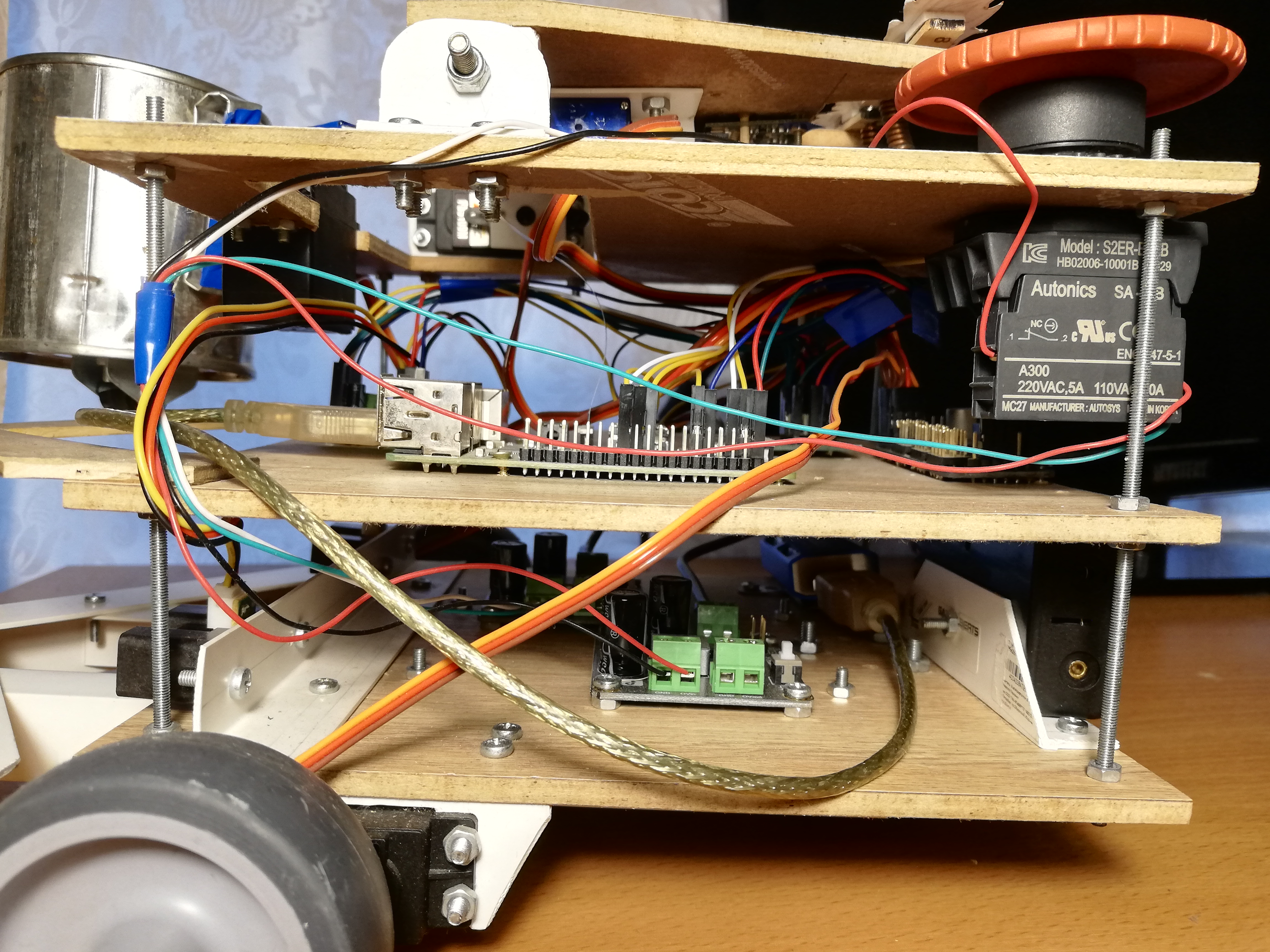
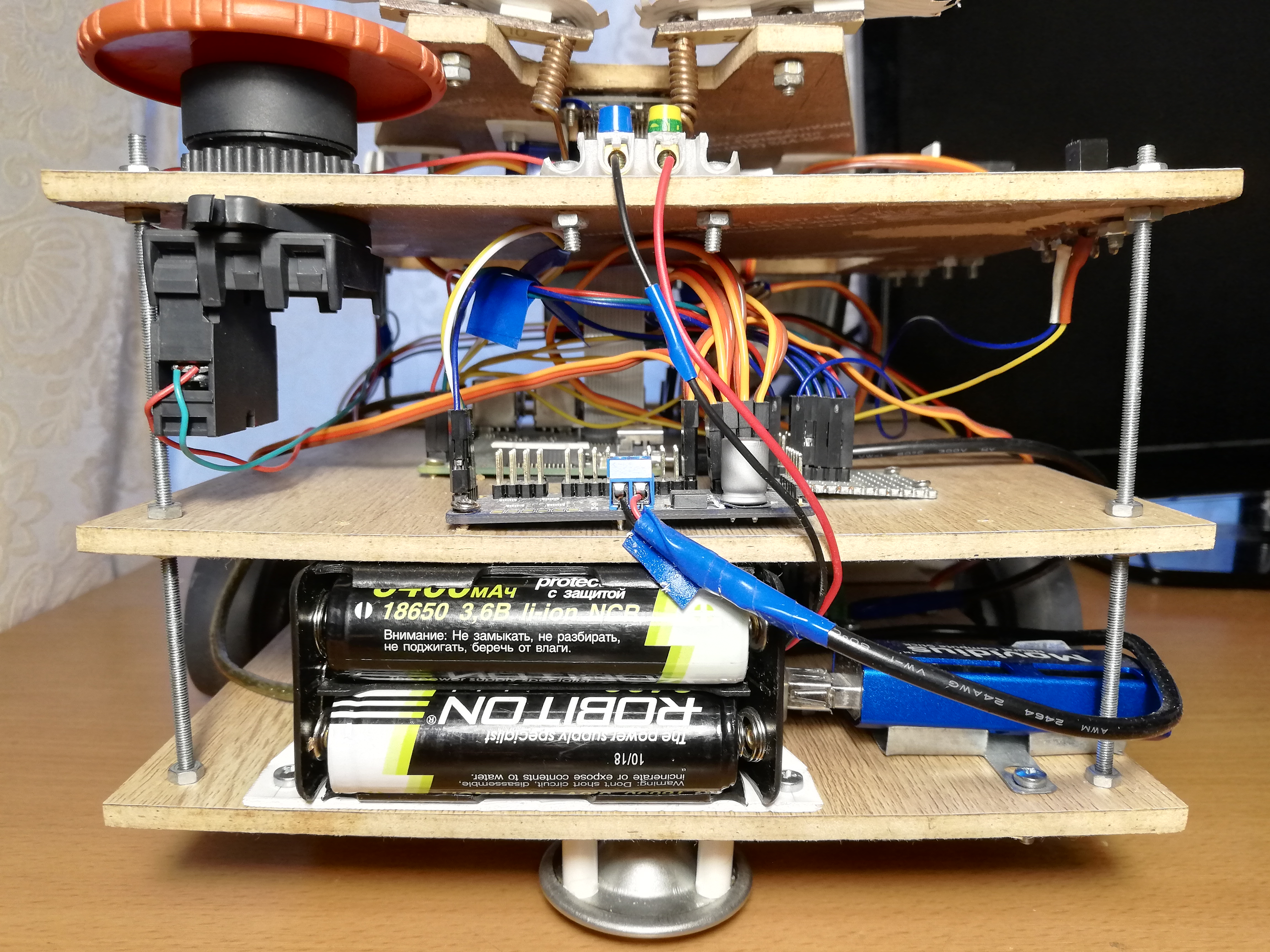
In total, it can be estimated that 1.5-2.5 amperes should be enough, provided that all the servos do not move simultaneously under heavy load. At the same time, Raspberry needs a conditional 5 volts of voltage, and for servos - 4.8-6 volts. It remains to find a power source that meets these requirements.As a result, I decided to power the robot from 18650 format batteries. If you take two ROBITON 3.4 / Li18650 batteries (3.6 volts, 3400 mAh, maximum discharge current 4875 mA) and connect them in series, they can produce up to 4.8 amperes at a voltage of 7.2 volts. With a consumption current of 1.5-2.5 amperes, they should be enough for an hour or two.Batteries, by the way, have a catch: in spite of the indicated form factor 18650, their sizes are far from mm - they are several millimeters longer due to the built-in charging control circuit. Because of this, I had to stab the battery compartment with a knife so that they fit there.It remains only to lower the voltage to 5 volts. For this, I use two separate step-down DC-DC convertersDFRobot Power Module. This piece of iron allows you to lower the voltage at an input voltage of 3.6-25 volts and a voltage difference of at least 0.6 volts. For convenience, it has a switch that allows you to select exactly 5 volts at the output, or you can configure an arbitrary output voltage using a special regulator. I set both converters to 5 volts; one of them feeds Raspberry through a Micro-USB connector, and the second feeds servos through PCA9685 terminals. This is necessary in order to maximize the power supply of the logical and power parts of the robot so that they do not interfere with each other.At the debugging stage, I used a Chinese 9 volt, 2 ampere power supply instead of the batteries, and it was enough for the robot to work - I connected it, like the batteries, to two DC-DC converters. Therefore, for convenience, I made terminals on the robot, to which you can connect a power supply or battery compartment to choose from. This helped a lot when I completely rewrote all the code on ROS, and I had to debug the robot for a long time, including servos.For convenience, I also had to make a "power bus" - in fact, just a piece of the board with three rows of connected pins for ground, 3.3v and 5v, respectively. The bus connects to the corresponding Raspberry pins. Only IR rangefinders are powered from the 5v bus, and MCP3008 and PCA9685 from the 3.3v bus.And of course, according to the good old tradition, I put the Big Red Button on the robot - when it is pressed, it simply interrupts the entire power circuit. It was not necessary to use it for an emergency stop, but turning on the robot with the help of a button is really more convenient.Lower platform, from left to right: battery compartment, NCS, DC-DC converters, servo drives with wheels, rangefinders.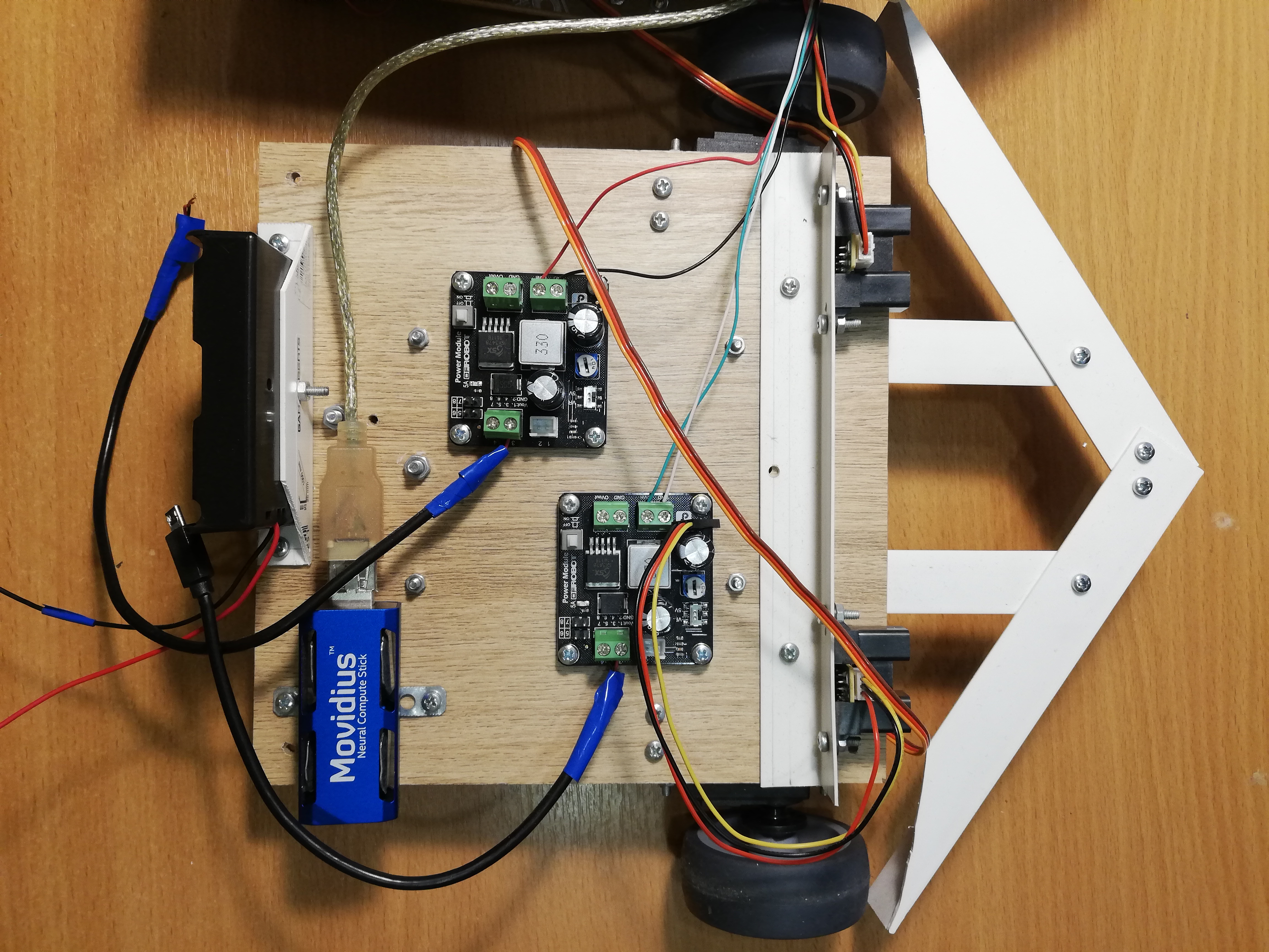
Robot control
There is no Wi-Fi on the Raspberry Pi 2B, so I have to connect via ssh via an Ethernet cable (by the way, this can be done directly from the laptop, without using a router ). It turns out this scheme: we connect via ssh via the cable, start the robot and pull off the cable. Then it can be returned to its place to access the Raspberry again. There are more elegant solutions, but I decided not to complicate.So that the robot can be easily stopped without turning off, I added a massive Soviet switch (from a submarine?) To it, when you turn it off, the program ends and the robot stops.The switch connects to the ground and to one of the Raspberry GPIO pins, and you can read from it using the WiringPi library :wiringPiSetup();
pinMode(PIN_SWITCH, INPUT);
pullUpDnControl(PIN_SWITCH, PUD_UP);
bool value = digitalRead(BB_PIN_SWITCH);
It is worth noting that with this connection, the voltage on the pin must be pulled up to 3.3v, and at the same time it will produce a high signal in the open state, and a low signal in the closed state.Putting it all together
ThreadsNow all of the above needs to be combined into one program that controls the robot. In the first version of the robot, I did this using threads ( pthread ). This version is in the master branch , but the code there is pretty scary.The program works in four threads: one thread takes frames from the camera and starts the detector on the NCS; the second stream reads data from rangefinders; the third thread monitors the switch and sets the global variable is_runningtofalseif it is off; The main thread is responsible for the robot behavior and servo control. Threads have pointers in common with the main thread, by which they write the results of their work. I restricted the vectors that store information about the faces found by the detector to the mutex, and declared the other, simpler common variables as atomic. To coordinate the flow of the face detector with the main thread, there is a flag face_processedthat is reset when a new result comes from the detector, and rises when the main thread uses this result to select a behavior - this is necessary in order not to process old data that may not be relevant after moving.The ROSversion with streams worked fine, but I started all this in order to learn something, so why not at the same time masterRos ? I have been hearing this framework for a long time, and I even had to work a bit with it on a hackathon, so in the end I decided to rewrite all the code on ROS. This version of the code lies in the default branch of ros and looks much more decent. It is clear that the implementation on ROS will almost certainly be slower than the implementation on the flows due to the overhead of sending messages and everything else - the only question is how much?ROS conceptROS (Robot Operating System) — , , , .
, , , (node), , , .
(topic) (message) , - .
— (service). , , . « », .
.msg .srv . .
ROS
.
For my robot, I did not use any ready-made packages with algorithms from ROS, I only designed the robot code in a separate package consisting of five nodes communicating with each other using messages and ROS services.The simplest node switch_node,, monitors the state of the switch. As soon as the switch turns off, the node begins to spam uninformative messages of the type boolin the topic terminator. This is a signal to the main node that it is time to complete the work.The second node,, sensor_nodeperiodically reads the readings of both IR rangefinders and sends them to the topic in sensor_stateone message. Also, this node is responsible for signal processing: scaling by calibration factors and moving average.Third knotcamera_nodeHe is responsible for everything related to faces: he takes images from the camera, processes them, receives the results of the detector, passes them through the tracker, and then finds the face closest to the center of the frame - the robot does not use the rest anyway, but you want to make smaller messages. The messages that the node sends to the topic camera_statecontain the frame number, the fact of having a face (because you also need to know about the absence of a face), the relative coordinates of the upper left corner, the width and height of the face. This is how the description of the type of message in the file looks like DetectionBox.msg:int64 count
bool present
float32 x
float32 y
float32 width
float32 height
The fourth node,, servo_nodeis responsible for the servos. Firstly, it supports a service servo_actionthat allows one of the actions to be performed by servos by its number: to put the entire node in its initial state (eyebrows, bank, head, stop the chassis); transfer the head to its initial state; shake the jar; depict with one eyebrow one of three expressions (good, neutral, evil). Secondly, using the service, servo_speedyou can set new speeds for both wheels by sending them in the request. Both services do not return anything. Finally, there is a service servo_head_platformthat allows you to rotate the head and / or chassis a certain angle relative to the current position. This service returns trueif it was possible to turn the head at least partially, andfalseotherwise, in the case when the head is already at the border of the permissible angle, and we are trying to turn it even further. If both angles in the request are nonzero, the service rotates asynchronously, as indicated above. In the main loop, the servo node does nothing.Here, for example, is a description of the service servo_head_platform:float32 head_delta
float32 platform_delta
---
bool head_success
Each of the listed nodes supports a service terminate_{switch, camera, sensor, servo}with an empty response request, which stops the operation of the node. It is implemented in this way:Some code...
std::atomic_bool is_running;
bool terminate_node(std_srvs::Empty::Request &req, std_srvs::Empty::Response &ignored) {
is_running = false;
return true;
}
int main(int argc, char **argv) {
is_running = true;
...
while (is_running && ros::ok()) {
}
...
}
The node has a global variable is_running, the value of which determines the main cycle of the node. The service simply resets this variable, and the main loop is interrupted.There is also a main node beggar_botin which the basic logic of the robot is implemented. Before the start of the main loop, it subscribes to topics sensor_stateand camera_statesaves the contents of messages in global variables in callback functions. He is also subscribed to the topic terminator, the callback for which resets the flag is_running, interrupting the main loop. Also, before the cycle starts, the node announces the interfaces for the services of the servo node and waits a few seconds for the other nodes to start up. After the main loop ends, this node calls the servicesterminate_{switch, camera, sensor, servo}, thus turning off all other nodes, and then turning it off itself. That is, when the switch is turned off, all five nodes complete the operation.Switching to ROS forced me to change the structure of the program quite a lot. For example, earlier it was possible to change the wheel speed with a high frequency, and this worked fine, but the ROS service works an order of magnitude slower, so I had to rewrite the code so that the service was called only when the speed really changes (in "lazy mode").ROS also allows you to quite conveniently run all the nodes of the robot. To do this, you need to write a .launch launch file listing all the nodes and other attributes of the robot in xml format, and then run the command:roslaunch beggar_bot robot.launch
ROS vs. pthreadNow, finally, you can compare the speed of the ROS version and the pthread version. I do it this way: the thread / node responsible for working with the camera considers its FPS (as the slowest element), provided that everything else also works. For the pthread version, I consistently got FPS 9.99 or so, for the ROS version it turned out about 8.3. In fact, this is quite enough for such a toy, but the overhead is quite noticeable.Robot behavior
The idea is quite simple: if the robot sees a person, he must drive up to him and shake the can. Shaking the jar is quite simple and fun, but first you need to get to the person.There is a function follow_facethat, if there is a face in the frame, rotates the chassis and the head of the robot in its direction (only the face closest to the center is taken into account). This is necessary so that the robot always keeps its course on a person, if he is in the frame, and also looks directly in the face when he shakes a jar.The camera_statesame variable is used to synchronize this function with the topic .face_processed, as in the version with streams. The idea is the same - we want to process data only once, because the robot is constantly moving. The function first waits until the callback of the topic with the detections lowers the flag that the last frame has been processed. While she waits, she constantly calls ros::spinOnce()to receive new messages (in general, this should be done wherever the program expects new data). If there is a face in the frame, the angles are calculated, which need to rotate the platform and head - this can be done by knowing the relative coordinates of the center of the face and the field of view of the camera horizontally and vertically. After that, you can call the service servo_head_platformand move the robot.There is one subtle point: information about the position of the face lags behind the actual movement of the face and may lag behind the movements of the robot itself. Therefore, the robot can overestimate the angle of rotation, because of which the head begins to move back and forth with increasing amplitude. To prevent this, I make delays after the move (300 ms), and also skip one frame following the move. For the same purpose, the angles of rotation of the chassis and head are multiplied by a factor of 0.8 (the P-components of the PID controller make sense ).Functionfollow_facereturns the status of a person. A person can: be absent, be close enough to the center, be too far away from the robot; another option - when we turned the robot and do not know what happened to the face (in the search process); there is still a rare case when the head is on the border, which is why it is impossible to turn to the face.A rather simple thing happens in the main loop:- Call
follow_faceuntil the person has a certain status (any, except for “in the search process”). At the end of this step, the robot will look directly at the face. - If the face is found and it is close:
- Shake the can;
- Find the face again;
- If the face is in place, make a good expression with eyebrows and shake the jar again;
- If the face has disappeared, make an angry expression with eyebrows;
- Turn around, go to the beginning of the cycle.
- If there is no person (or it is far away) - navigation around the room:
- If there are far from obstacles on both sides, drive forward (if the face was found, but turned out to be too far, the robot will go to the person);
- If obstacles are close on both sides, make a random turn in the range ;
- If the obstacle is only on one side, turn in the opposite direction at a random angle ;
- If the forward movement continues for too long (possibly stuck), pull back a little and make a random turn in the range ;
This algorithm does not claim to be a strong artificial intelligence, however, randomized behavior and a wide bumper allow the robot to get out of almost any position sooner or later.Conclusion
Despite its apparent simplicity, this project covers many non-trivial topics: work with analog sensors, work with PWM, computer vision, coordination of asynchronous tasks. Plus, it's just insanely fun. Probably, further I will do something more meaningful, but more with a bias in deep learning.As a bonus - the gallery: