In a previous article, the device of an analog video camera was examined in great detail in order to create its own firmware. As already mentioned, the camera has a microcontroller of unknown origin. It is much richer than the usual AVRs: it has two supply voltages 3.3V and 1.8V, and also, it has a DSP function. I came to this conclusion when I thought about the implementation of the autofocus algorithm. Nevertheless, I did not prefer complex MKs like STM32 and others, if only because I never worked with them at all. I definitely made the decision that I will use one of the AVR MKs to implement my firmware. Therefore, already at this stage I began to realize that the implementation of the autofocus function will not be very easy to handle, or rather, impossible.My choice fell on the ATmega128 MK, since it was he who fell into my arm. The ATmega8 MK will obviously not be enough in terms of the number of conclusions, especially since, just in case, I decided to reserve a whole MK port for input of the digital video stream from the video processor. First of all, I figured out what functions will be in my own firmware, in particular, functions that were not in the original firmware, and which functions will have to be neglected.Let's consider a variant of the autofocus algorithm for analyzing a digital video stream. I managed to find out that the video stream data is an alternation of bytes synchronized with the “CK” pulses. Bytes of the video stream encode the levels of the Y, Cr, Cb components of the video signal with 8-bit gradation (256 levels). That is, the digital video output from the video processor of this camera is component-multiplexed. Information on brightness (Y) is contained in every second byte of the video stream, and information on color is two times less frequent. That is, information on the color difference signal of red Cr is contained in every fourth byte, as well as information on the color difference signal of blue. Thus, the stream represents the following sequence: Cb0, Y0, Cr0, Y1, Cb2, Y2, Cr2, Y3, Cb4, Y4, Cr4, Y5, .... I.e,while information about the brightness of each pixel comes without gaps, information about the color of pixels comes in componentwise in sequence. This thinning is due to the properties of insensitivity to the color of small details and a reduction in the color band in the video signal. These properties are used in analog television and video digitization. The above “compression” (color subsampling) has a component ratio of 4: 2: 2.For the autofocus algorithm to work, it is enough to analyze only the brightness component, which is also easy to achieve by intercepting the video stream “byte by byte”. If the CK frequency is about 18 MHz, then CK / 2 is 9 MHz, which would seem to be quite achievable for the ATmega128 MK. The horizontal and vertical synchronization pulses enable the controller to “count” and analyze any area of the image. Perhaps, for the autofocus algorithm, it is enough to analyze only the center of the raster. Obviously, the better the focus, the sharper the image, and therefore the wider the frequency band of the video signal (more RF components). That is, it is possible (even necessary) to apply the Fast Fourier Transform (FFT) algorithm to fragments of a digital video stream and analyze the RF components. In this case, you need to twist the focus focus every time,using the “half division” method as a mathematical optimization method. Thus, you can achieve the best result.I did not bother with the autofocus function, considering that it was impossible on MK with a simple architecture, although, in any case, I reserved a port for digital video. Instead of autofocusing, I decided to implement a number of other functions that were not available in the original firmware. But for this, the video camera will have to be limited to stationary conditions, which is typical for video surveillance. It is assumed that the camera will subsequently be able to rotate in the horizontal and vertical plane using special mechanisms, both automatically and manually. When the camera is automatically aimed at a specific object, the spherical coordinates of which will be pre-stored in the memory of the control device, the “coordinates” of the zoom and focus will also change, which will also be pre-selected and stored in the memory.Management can be organized according to the PELCO-D protocol, moreover, in the specification of this protocol there is a special team for this business. The coordinates of the zoom and focus, of course, will be "paired" for a specific distance. That is, an object that will be located at a given distance will be in focus.Before you start writing a firmware program, you need to think about which peripherals of MK and what conclusions will be involved. Then you need to think about how to place and fix the board with its own MK inside the camera. And so that it was as convenient and maintainable as possible. I decided to use a board with MK, the conclusions of which will be completely routed to the left and right side. The board will be located at the bottom of the camera, where there is little space, and will be held on a detachable connection. At the same time, there will be “pins” of the connector on the board itself, and there will be mating sockets on the sides of the camera. For the response sockets, I decided to make two more adapter boards, the size of the side of the camera. The lamellas of these cards go to the upper side of the camera, directly to the main board. It is assumed that each lamella will be wired to the desired point on the main board of the camera.During the development of the board with MK, I had the idea to supplement the camcorder with a clock (RTC), and I highlighted the I2C line, placed on the RTC DS1307 board (I already know what the hell) with quartz and a battery and, just in case, EEPROM 24AA512, which were by hand. Also on the board at the top edge are connectors for connecting SPI and JTAG programmers. On the original motherboard, MK is clocked from 12 MHz quartz. It’s the same for me. In general, it is better to put quartz at 11.0592 MHz there for clear UART operation. The distances between the "combs" of detachable joints I carefully calculated beforehand. I decided to feed MK from the five-volt “Krenka”, which will be screwed onto the frame under the main board (it will also serve as a heat sink). Power will be taken from the input voltage 12V immediately after the fuse FB801, as shown in the figure.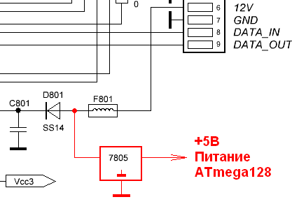 Fig. 1. Power management of the microcontroller.While drawing boards in "SprintLayout", I wondered the purpose of each pin of the MK, which is output "out" to the connector. The result is such a picture.
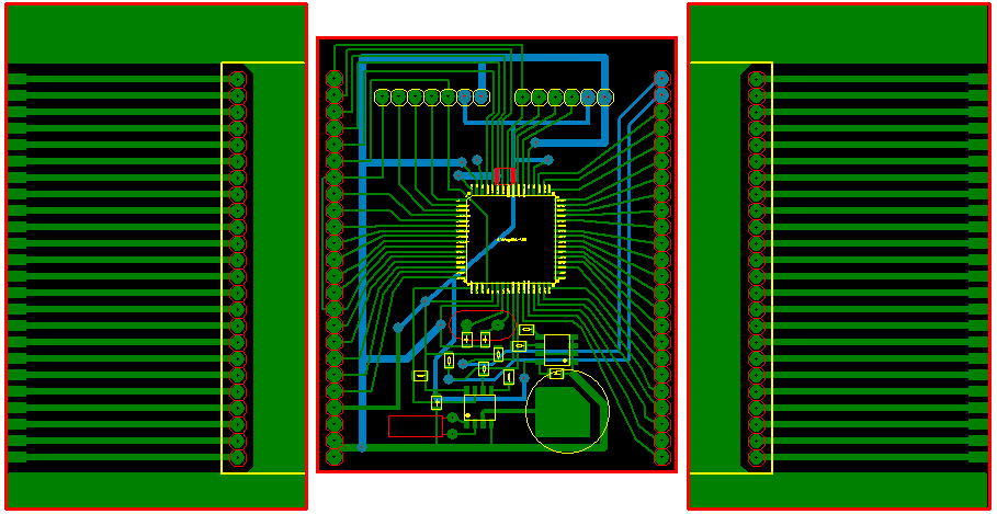 Fig. 2. Sketches of additional printed circuit boards.To tell you the truth, I drew the side boards (along the edges) at the stage of writing this article. But in fact, I made them with a cutter. It turned out not the most successful option. And the board itself with MK was made crookedly. I somehow screwed the side auxiliary boards to the sides of the camera frame, soldering flux nuts to the copper surface of the PCB. The fact is that there is very little space on the sides, and the camera’s lid is practically “tightened” back to back.The figures below show the distribution of the conclusions of the MK, as well as their purpose.
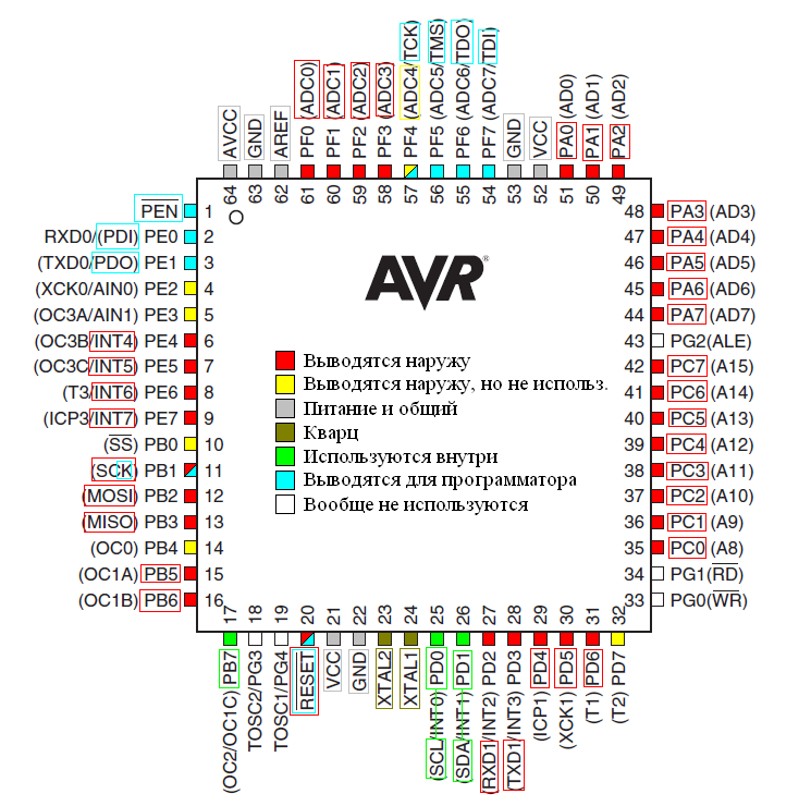 Fig. 3. The purpose of the conclusions of the microcontroller.There are many points to comment on.For the SPI programmer (STK200 +), the output “PEN” was unnecessary. Activation takes place by “RESET”, as usual. But instead of “MISO” and “MOSI”, the MK has a separate interface (PDI / PDO), and the “CLK” line is combined.As the reference voltage for the ADC, I chose the same 5V, from which the MK itself is powered. I tried to get separately 3.3V (as in the original circuit), but at the same time there were pitfalls. And in order to switch to the 5V reference voltage, you need to slightly change the circuit, as shown in the figure.
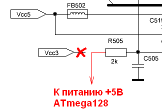 Fig. 4. Translation of the buttons on the 5V reference voltage.That is, you need to unsolder one side of the R505 resistor from the 3.3V supply side, and instead apply 5V to it from the MK power line.Of the conclusions of MK, which are used only inside the designed board, only three are involved. A 1 Hz pulse signal with RTC arrives at PB7 to update the time. Pins PD0 and PD1 are allocated to the I2C bus. It will be implemented programmatically using the CVAVR library “i2c.h”, despite the fact that a hardware i2c (TWI) interface is attached to these outputs.The “RESET” MC pin is output, but the MK reset will occur on its own without an external reset chain.It was understood that the HD and VD clock pulses would arrive at the MK via external interrupt ports for the accuracy of reading the video field. However, excluding the autofocus function, they are no longer needed. Signals from the zoom and focus limit switches come to neighboring ports of external interrupts.Port “A” MK is reserved for the digital video stream. Port "C" is fully reserved for SD.Pin PD4 is used for switching TX / RX RS-485. There was no switching in the original circuit: the 2nd and 3rd legs of the MAX485 chip were on the ground. The original MK was only able to receive data for controlling the camera via PELCO-D. I decided to make a small upgrade. The idea was this. If the camcorder hangs high and in a closed casing, it will simply be impossible to quickly update the firmware. And such a need will surely arise: eliminating various bugs and improving functionality will become a regular practice for the first time. Therefore, I came up with the idea to implement a bootloader for MK, and already using it remotely update the firmware via RS-485. And in this case, a two-way exchange is very desirable. About the bootloader will be a separate part of this article. And in order to connect the MAX485 (2 and 3 legs) to this MK pin,you need to make a small change to the first and second board. These boards are connected by a loop cable, on the connectors of which there is an unused “IRL” contact for backlight control. On the second (main) board, you need to unsolder the R520 resistor and instead solder the wire that goes through the adapter board to the ATmega128 MK to the corresponding output instead. And on the first board you need to unsolder and bend up 2 and 3 legs of U202, solder them together and pull them from the wiring to the free output of 1 connector J302. These operations for changing the circuit are shown in the figure.which will go through the adapter board to the ATmega128 MK to the corresponding output. And on the first board you need to unsolder and bend up 2 and 3 legs of U202, solder them together and pull them from the wiring to the free output of 1 connector J302. These operations for changing the circuit are shown in the figure.which will go through the adapter board to the ATmega128 MK to the corresponding output. And on the first board you need to unsolder and bend up 2 and 3 legs of U202, solder them together and pull them from the wiring to the free output of 1 connector J302. These operations for changing the circuit are shown in the figure.
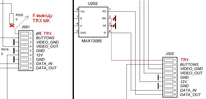 Fig. 5. Organization of the TRX line for controlling the TX / RX MAX485.There are two UART interfaces on board the ATmega128. In this case, you have to use the second interface (pins 27, 28), since the first interface on pins (pins 2, 3) is combined with the interface for the SPI programmer.On the board, almost all the conclusions of the MK are involved. The conclusions of port “G” turned out to be unused. By the way, it was possible to implement the clock programmatically on the basis of MK. It provides a sleep mode with the use of a battery for counting time when the main power is off. There are even conclusions for connecting a separate low-frequency quartz. However, I did not bother with this, slapping the DS1307.The figure below shows the purpose of each output of the board with MK. In addition, it is conditionally marked what and on which side of the main board the wires from each pin will be soldered. It is also necessary to give some comments.
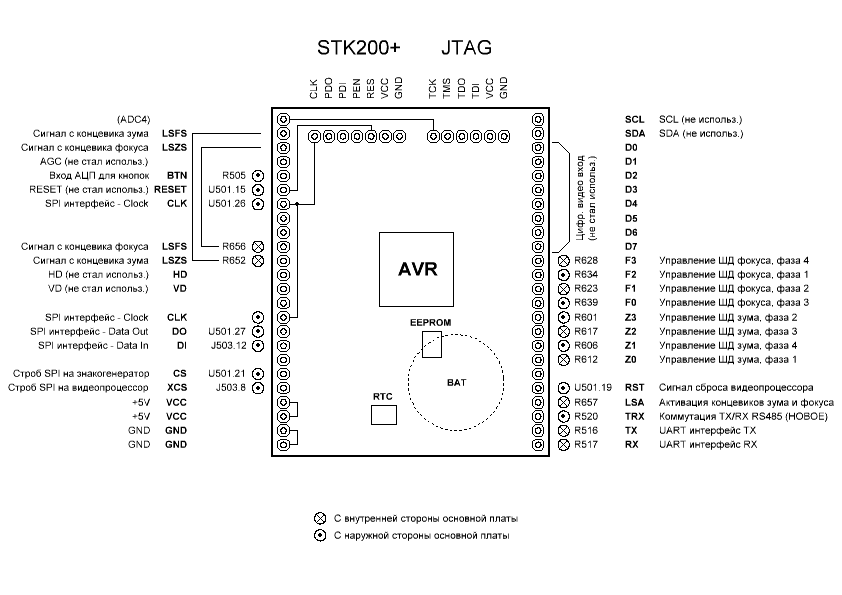 Fig. 6. Assignment of conclusions of an additional payment with MK.Signals from the zoom and focus limit switches come not only to the interrupt ports, but also to the ADC inputs. The fact is that even at the stage of the study of SD, I noticed such a feature. If the zoom or focus mechanism is at “zero”, the output signal from the trailer can take an “intermediate” state. To better capture such rare cases, I decided to use the ADC. Of course, this is not a very competent approach, but by doing this I quickly got out of the problem that sometimes arose at the initialization stage in my test firmware. Thus, I increased the stability of the algorithm.The SDA / SCL signals from the I2C are just plugged into the connector, just in case, and they are not used outside of this board.The names of each pin for the control of the ID are signed according to the actual connection. Connecting data, looking ahead, was finally corrected at the debugging stage. There was a lot of confusion, but the errors were only in the alternation of phases accurate to the reverse, and not in their ordering. Alternations “4-1-2-3” (for zoom) and “2-3-4-1” (for focus) are one and the same, as well as “1-2-3-4”, which and was taken as a basis.At the end of the article
 (so as not to disgrace) two photos are presented. The first one is the bottom view of the camcorder with a view of the additional circuit board. The second one is a view from above from above on the main board of a video camera with a sealed-off standard MK (microprocessor, to be more precise), a bunch of wire jumpers and other snot.I wrote the program (firmware) together with its preliminary testing in the ISIS 7 Professional (Proteus) program.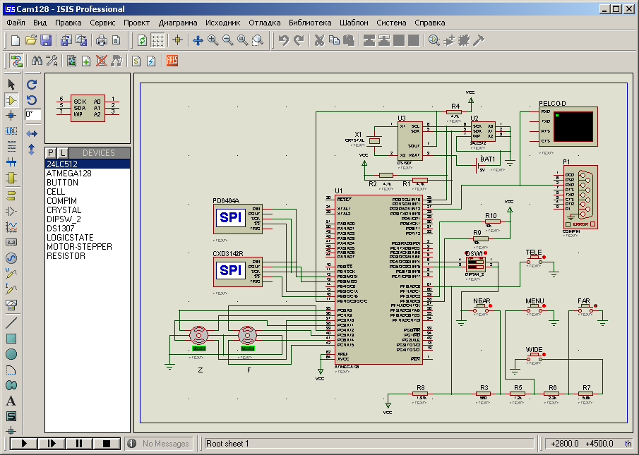 Fig. 7. View of the project in Proteus.Instead of the unique chips of the character generator and video processor (which, of course, are not in Proteus), I installed SPI debuggers. With the help of them, it is convenient to control the bytes that MK sends by SPI. But the real reaction to these bytes is controlled directly on the hardware. With Proteus, you can monitor and debug PELCO-D commands coming from a real DVR. To do this, as an option, you need to connect the DVR to the computer’s COM port through the simplest one-way adapter RS485-> RS232.Then I started developing and modeling. Excel helped a lot with this.First you need to decide on the timers and their configuration. One timer - to realize the rotation of the stepper motor and the implementation of repeated operations of the buttons while holding them. When holding this or that button during settings through the menu, the operation of the SD will be excluded. And when you hold one of the zoom or focus control buttons outside the menu, the SD rotates with the corresponding time parameter. Thus, there are no conflicts. I planned to use the second timer to implement PWM for the SD, but over time I decided to abandon it. Indeed, in my case, when there is no autofocus, there is no need for PWM. Moreover, the transmission mechanism has a helical structure, therefore, at rest, you can not "hold" the SD by direct current, the mechanism will not creep anywhere.Then you need to revise the alphabet of characters of the character generator, according to the datasheet, and compare it with the standard alphabet ASCII. The alphabet of the character generator consists of 128 characters, which is half the size of the last. For example, the Cyrillic characters in the character generator are completely absent, but there are special characters that are characteristic of its application (sun, hourglass, little man, note, phone, etc.). I made an array of “smb [256]” of 256 elements, placing it in the EEPROM MK. The notation smb [i] = adr means that at the address adr in the character generator there is a character with the ASCII code i. And if the symbol i is not in the alphabet of the character generator, then the value of the array element refers to the "space" with the address 0x7E. That is, almost half of the elements in the array have a value of "0x7E". This array is presented in table form in the figure below.
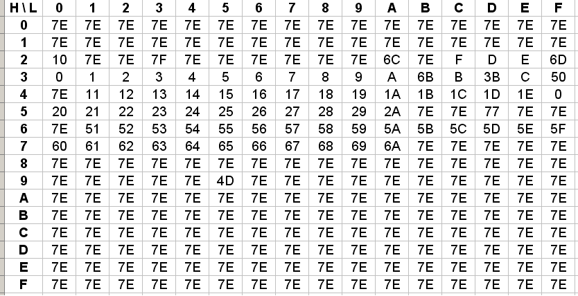 . 8. ASCII PD6464A.Next, you need to consider how to process buttons through the ADC. According to Ohm's law, it is easy to calculate the voltage values at the input of the ADC when you click on a button. After that, it is easy to calculate the boundaries of the intervals, the middle of which will be the same stress values. In total, six intervals are obtained: five of them correspond to each button and one to the absence of pressing (no button is pressed). At the hardware level, the ADC MK periodically analyzes the voltage value from the buttons. The timer for anti-bounce can be implemented based on the calculation of the ADC clock cycles, which I did. At the debugging stage, this part of the program had its pitfalls. I think that it’s not worth writing details. To achieve the clear work of this functionality, I had to tinker a long time. The button recognition function is placed in the ADC interrupt section, and on its output is the button number,depression flag and release flag. Further processing of the buttons occurs in the main program cycle. The button polling frequency (ADC frequency) was 12000/128 = 93.75 (kHz), where 128 is the maximum possible divider.Then I compiled an array of UART register values UBRR1 of the UART configuration, depending on one or another PELCO-D baud rate, which can be selected from the list in the settings via the menu. These values can be calculated using the formula from the datasheet on the MK, and can also be obtained using the AVR Wizard auto-configurator.Then I started modeling the menu. This is the main and time-consuming stage of writing a program. In principle, I was not going to repeat the menu of the standard firmware, except for this, I decided to complicate it to a hierarchical structure (section in the section). Below is a description of the model and the definitions of the menu that I made for myself.
Can not read.
.
.
.
«MENU».
«» .
«» «» .
«» .
«» .
( ) , .
« », .
:
— ;
— ;
— ;
— .
, , .
<>.
.
"<..>".
«».
, .
( ) .
"<..>" .
, .
.
.
.
.
"<•>" ( ).
"< >" ().
«».
.
.
«l*l» (, «l»).
«l l» (, «l»).
«».
, .
.
.
.
: «000», «00», «0».
.
: ": ".
— ( ) .
, , «» «».
«» 1.
«» 1.
.
.
Thus, menu navigation is somewhat similar to navigation through files and folders through “Total Commander”. The implementation code for this menu model is not very complicated, but very cumbersome. There are two key variables: the number of the active page and the number of the active position on the page. For both variables, two “switch-case” functions work in each other. This pair of functions is involved in the process of pressing the buttons "Left", "Right" and "Menu". In each place (for each button, page and current item) certain actions are registered. Each menu page has a function that implements the display of the page on the screen with all the inscriptions and parameters. Before implementing the page output functions, I previously modeled them in Excel, as they say, “by cells”.So the coordinates of the cells of each symbol on the screen field are presented more clearly, and this information is necessary at the programming stage. In the figure below, as an example, I gave the view of page 9, on which the PELCO-D baudrate is selected from the list. The interface element on the page is a radio button. In addition to it, the first paragraph <..> is to exit this section.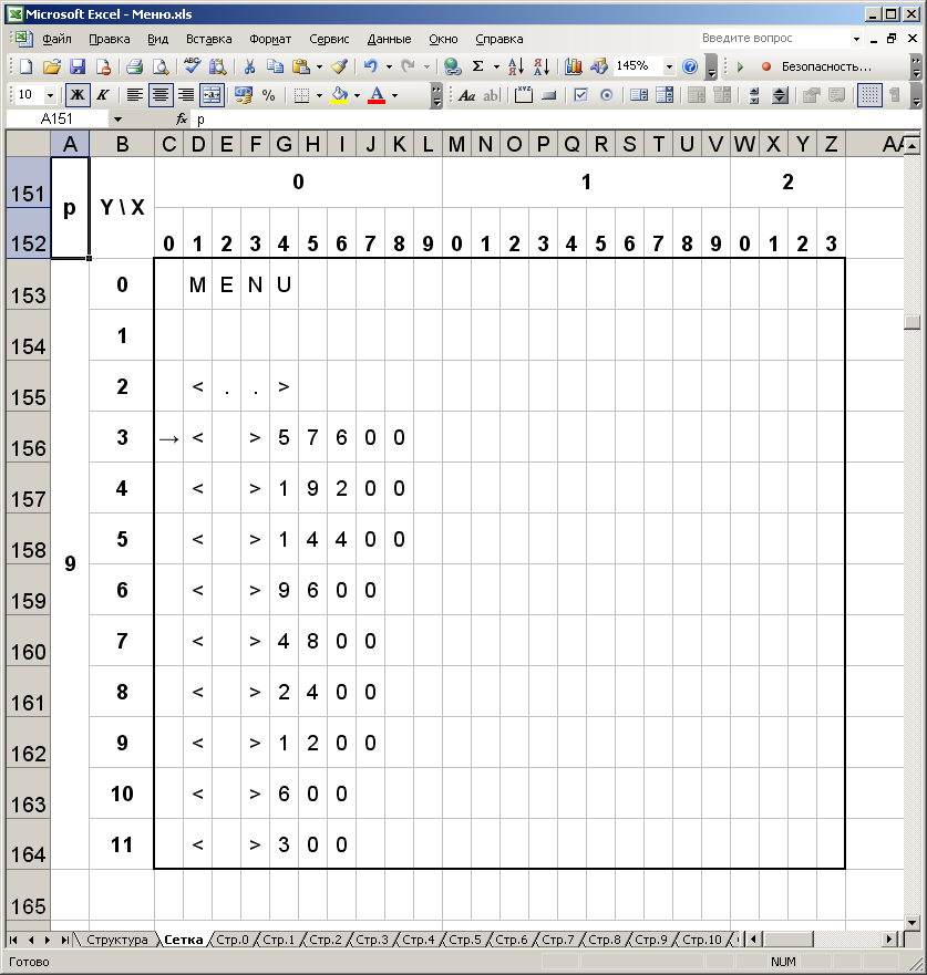 Fig. 9. Modeling the OSD in Excel.I also made an array that reflects the number of points on each page. It is used in the processing of pressing the Up and Down buttons. This is done to reduce code and avoid using the switch-case function.Repeated virtual presses while holding the buttons are implemented in the body of the timer interrupt by the “switch-case” function, which works on an integer variable, which is a flag. The flag value is unique for each action of a button on a specific page and a specific menu item. It is assigned to the flag as a serial number only in those places where virtual clicks are needed. At the same time, inside the “switch-case” function (in the body of the timer interrupt) are placed copies of functions that implement the actions of the buttons. To save memory, it was possible to place “shortcuts” (links) on regular calls to the button processing function. It’s even more reasonable, but at that moment I didn’t have the patience to think about how to do it better, because I wanted to finish the project as soon as possible. And the memory in ATmega128 turned out to be quite a lot.Finally, I implemented “libraries” for working with a video processor, character generator, and RTC DS1307 with the necessary functions. After that, I determined the addresses of the EEPROM MK to store this or that information. The first 32 bytes are reserved for storing menu settings information. The next 32 bytes are reserved for storing text that can be displayed on the screen or changed using the standard command “Pelco-D Write Char. To Screen. " The next 256 bytes of the EEPROM area are reserved for the alphabet (conversion of a character from ASCII to an address for a character generator, as mentioned above). Finally, the next 128 bytes are reserved for storing “presets” (templates) of zoom / focus. I introduced this feature due to the lack of autofocus. I wrote about this at the beginning of the article. A total of 32 templates. The coordinates of the zoom or focus are encoded in two bytes.Separately, it is worth writing about the implementation of SD management. The rotation of the SD is achieved by calling the functions StepF () and StepZ () in the timer interrupt block. The rotation speed is determined by the configuration of this timer. And the implementation of the above functions implements the promotion of focus or zoom (respectively) at a minimum step. During the rotation of the zoom lens and focus, their final positions are controlled. The position of the maximum focus and the position of the minimum zoom are represented in the program by constants (280 and -600, respectively). But the position of the minimum focus and the position of the maximum zoom - in the form of variables F_min and Z_max (more precisely, functions). This approach was facilitated by a non-rectangular work area with a cut-off lower right corner. To calculate the values of F_min and Z_max, piecewise-defined functions F_min (Z) and Z_max (F) are used. Besides,when the SD zoom rotates in the positive direction at Z (zoom coordinate)> 500, the SD focus rotates simultaneously in the same direction if the latter has coordinates <(- 180). That is, the maximum zoom position, in principle, is not limited by the current focus position, but is limited by the number 600. Simply, two SDs rotate simultaneously when the corresponding angular boundary of the pentagonal region is reached, and movement at this stage occurs along the “cut side” (if interpreted graphically) ) From the point of view of mechanics, this is equivalent to the process described in the previous article, when, in the absence of SD and when moving the zoom and focus nodes manually, the zoom node at the end of the path “pulls” the focus node. Due to the fact that the zoom coordinate dominates the focus coordinate (which is why I consider the F (Z) dependence,but not vice versa), I did not begin to implement a similar zoom “scrolling” procedure in the Step_F () function.In the original firmware, the speed of changing the zoom and focus had fixed values. This is not always convenient. In my firmware, I provided four values of the zoom and focus speeds (independently), which can be selected both through the menu and using the PELCO-D command assigned to this function. These four values are pre-selected at the debugging stage based on convenience, then they are entered into the firmware.The BD initialization function init_MR () is needed to bind the mechanics of the zoom and focus to the coordinate system. It is performed once every time you turn on the camcorder. The algorithm of her work is approximately the following. First of all, it is assumed that the zoom or focus is at the zero point, and an attempt is made to catch the bounce of the signal from the limit switches by external interrupt functions. I’ll note right away that if the zoom or focus is “at zero” (at the boundary of the optical limit switch), the signal at the output of the limit switch has an “intermediate” state between logical “0” and “1”. Such cases are very unlikely, but they cannot be ruled out. However, the interrupt function does not interpret a signal such as bounce. That is why I came to use the ADC MK, triggering signals from the limit and zoom limit switches on its two free channels. So,the first step is the "digitization" of signals from the limit switches with 8-bit accuracy. This is done using a single analog-to-digital conversion. It is worth remembering that the reference voltage in our case is 5V, and the logical level “1” from the limit switch is 3.3V. For a logical “0”, the ADC value will be zero, and for a “1” - 3.3 / 5 * 255 = 168. If the signal value from one or another trailer falls into the range, say, from 2 to 165 (a fuzzy interval is taken), this means that the corresponding node is already “at zero”, and the initialization procedure for this node can be stopped. Otherwise, by the logical value of the trailer signal (“0” or “1”), you need to determine in which part (half) the node is located. The direction of rotation of the SD will depend on this. One way or another, the SD should be rotated in this direction,so that the corresponding node moves towards the "zero" (limit switch). Thus, the rotation of the motor drive is started with the simultaneous calculation of the number of steps until the limit switch is reached. As soon as the corresponding limit switch is reached, which determines the function of external interruption according to the difference in the logical level, there will be a reverse rotation of the motor drive. It will rotate in the opposite direction by the same number of steps, thereby returning to its original position. The value of the number of steps for each BD with the corresponding sign will be copied to the corresponding variables before exiting the initialization function. The procedure described above occurs independently for focus and zoom within the same function (not in turn).The speed of rotation of the motor drive at the initialization stage is determined by a separate constant and corresponds to the maximum speed for confident correct rotation of the SM.Consider the example where, before turning on the power of the camera, the zoom was in the negative region, and the focus was in the positive region. The figure schematically shows the trajectory of the point (Z; F) during the initialization procedure of the stepper motor.
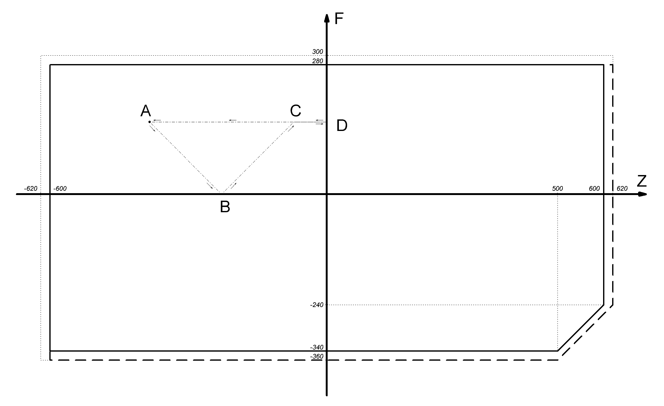 Fig. 10. The process of initializing the zoom and focus.Point A is the initial position of the zoom and focus. The movement of both nodes occurs in the direction of "zero" with the same speed (initialization speed). At point B, the focus reaches zero, as it was closer to zero than the zoom. Then the focus is reversed. At point C, the focus completes the initialization process, returning to its original position. At the same time, the zoom is still moving towards its “zero”. At point D, it reaches its “zero” and returns to its original position (point A).In addition to the init_MR () initialization function, there is a goto_zf (z, f) function. Based on the name, it is intended to switch from one preset to another, which I wrote about at the beginning of the article. The speed of rotation of the stepper motor during the transition is the same as during initialization. The transition process in zoom and focus is carried out simultaneously. That is, if it is required to go from the point (z1; f1) to the point (z2; f2), the simultaneous rotation of two SDs is started. If, for example, | f2-f1 | <| z2-z1 |, then the focus SD will stop earlier. This is demonstrated in the figure below.
 Fig. 11. The process of changing the zoom and focus when choosing a preset.Throughout the entire operation time of the stepper motor during the passage of the zero mark limiter, the corresponding coordinate is zeroed. And this despite the fact that theoretically this can not be done. However, in practice, there is still an error of 1-2 steps of the SD.It is worth adding that, unlike the original firmware, in my case, when controlling zoom and focus (both from the buttons and through PELCO-D), I provided for the possibility of step-by-step movement. This works as follows. When you click on any one of the 4 buttons for controlling the zoom or focus, the corresponding SD is rotated one step, thereby minimizing the movement of the zoom or focus node. If you do not release the button, then the normal rotation of the stepper motor will begin after a short period of time. This delay is selected empirically in advance. This feature is similar to virtual repeated presses while holding the button. Thanks to this feature, the problem of “sticking” the button when controlling zoom or focus on PELCO-D remote device via a poor Internet connection is eliminated. More precisely, the opportunity arises as rude,and fine-tuning the zoom or focus.The interpreter of the PELCO-D commands is made by the same analogy as in the device for switching loads via PTZ. I earlier devoted a separate small article on Habré to this simple device. Unlike the original firmware, zoom and focus control commands fully refer to pressing the corresponding buttons. That is, it is possible to “climb” the menu using the PELCO-D zoom and focus buttons. And in order to remotely call up the menu through PELCO-D, or rather, press the “MENU” button, I compared the aperture opening button with it, because this function is not used in this camera model. Thus, there are five basic PELCO-D commands for pressing, as well as five basic commands for releasing buttons. In addition, as I already wrote casually throughout the article, additional commands are processed: “Set Preset”, “Clear Preset”,“Go To Preset”, “Write Char. To Screen ”,“ Clear Screen ”,“ Set Zoom Speed ”,“ Set Focus Speed ”.Date and time with RTC are displayed in the lower left corner of the image by analogy with old VHS cameras, if this option is activated in the menu. In addition, in the menu you can select the output format, which I also provided in advance. Also on the screen next to the date and time it is possible to display the day of the week. In addition to the clock, the current coordinates of the zoom and focus are displayed on the screen as additional information. This option is needed primarily at the debugging stage.I’ll tell you about the functions of the menu that I implemented. Over time, if necessary, the menu will be revised: some functions can be removed, and some added. The menu structure that I drew in SPlan, with page views, is shown in the figure below. Red arrows - enter the section. Blue arrows - exit from the section. I did not draw blue arrows on each page of the menu, I drew only two for example.
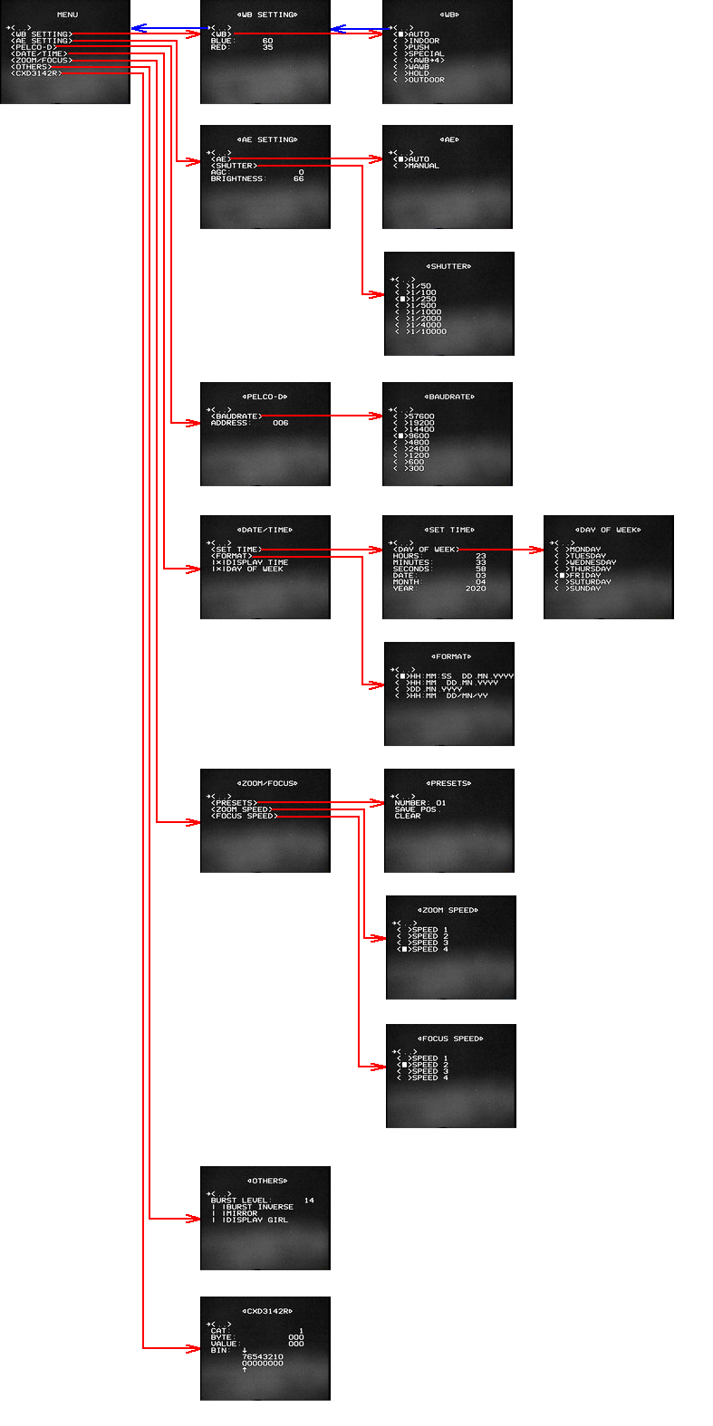 Fig. 12. The structure of the on-screen menu.Some sections of my menu are a bit like sections of the original. First of all, these are the first two sections: white balance and exposure. In the third section, you can specify the address of the PELCO-D camera and select the data rate (baudrate) from the list. The fourth section is devoted to date and time. You can set the date, time, day of the week, choose one of four display formats, and choose a display method. The fifth section - working with presets (templates) of zoom and focus, where you can call it by number, as well as erase or overwrite. Also in this section of the menu, you can choose one of four speeds for changing focus or zoom. The fifth section allows you to edit the parameters of the video processor, located in the byte 9 of category 3. This is the level and inversion of the burst component of the video signal, and video mirroring. The last section of the menu is for debugging.Using it, you can write to the video processor any value of any byte in any category. The value can be set in both decimal and binary form.Now I will say a few words about the bootloader. As I already wrote, the bootloader is needed for remote flashing the camcorder via RS-485. Initially, I thought to fully implement the bootloader myself. However, in order to save time, I decided to do with one of the already implemented ready-made downloaders that can be found on the Internet. Moreover, I have never used them, having an idea of them only at a theoretical level. One of the important criteria for choosing a bootloader is RS-485 support. Typically, AVR downloaders operate on UART RS-232. And the bootloader with RS-485 support differs only in that an additional output is allocated on the MK side for switching the RS-485 transceiver (for example, MAX485) during data transfer from the MK to the PC. When flashing MK, the bootloader transmits information about successful or unsuccessful recording to the computer. First bootloaderwhich I found allows you to record not only the FLASH memory of MK with firmware, but also EEPROM. In addition to writing, you can also read data. But this project with assembler source code was quite confusing and I did not understand it. Moreover, the main emphasis of this bootloader was aimed at the ability to flash multiple devices individually, without disconnecting them from the RS-485 network, accessing each device at an address previously sewn into it. I do not need such functional features, since I use a different topology of the RS-485 network, and it is possible to quickly switch the camcorder from DVR to PC. The second bootloader is the German Chip45. The source code is not in the public domain, it can be bought from the author. Instead, there are several hundred HEX files for different AVR MKs, different UART interfaces (if there are several, as in my case),RS-485 or RS-232 to choose from. In short, for all occasions. At the same time, the author notes that in the case of RS-485, the TX / RX switching pin is fixed and corresponds to the XCK UART pin of the controller interface, which is practically not used in UART. In my case, the 30th pin of the XCK of the second UART interface of the Atmega128 MK is PORTD.5 and is used to activate the zoom and focus limit switches. In principle, this function is not needed, because, as studies have shown, limit switches are always active, as I already wrote. And if necessary, you can transfer this function to any other free output MK. But, anyway, this bootloader also did not impress me, especially since I came across a more interesting bootloader called “AVR Universal Bootloader” of Chinese design. Like Chip45, it can only write and only in the FLASH memory of MK.But he has a large number of possibilities, and therefore I firmly decided to stay on it. It comes as an AVR Studio project with C source code. Due to the fact that I work in CodeVisionAVR, I had to install AVR Studio together with WinAVR. In order to get the HEX file for the bootloader firmware, you need to compile the project by making preliminary changes to the source code for your device’s own configuration and you need your own. Compilation of the project consists in launching a bat-file (batch file), in which the compilation commands are written. Thus, a project in AVR Studio is not required to be opened. Changes in the source code can be done either manually (at the programmer's level), or using the configurator. The role of the latter is an additional window of the utility that works with the bootloader, which is also attached.In the configurator, you can specify the MK pin for TX / RX RS-485 switching, the MK pin for the control flashing LED, the MK pin for entering the bootloader, the way to enter the bootloader, MK name and frequency, etc., you can’t list everything. In addition, the standard known HyperTerminal program can act as a utility for loading a user program in MK, that is, to work with the bootloader. It uses the Xmodem protocol to download firmware. And in order to conveniently and visually work with the bootloader through the text terminal, the special function “Verbose mode” is provided in the configurator. But despite the attractiveness of the hyperterminal, I decided to use the utility that came with the bootloader. The fact is that with the convenient Verbose function activated in the configurator, working through the terminal, I came across the following situation.Sometimes it happened when the data traffic in the line “collided” (both devices in TX mode), as a result of which the MAX485 in the camcorder became very hot and failed, or rather, not completely, but only the RX section (transmitting data via RS-485 to the camera) . Because of this, I abandoned HyperTerminal. And there is one more inconvenience. HyperTerminal does not work with HEX text files and only accepts a binary file. Therefore, I would have to apply an additional conversion from hex to bin. After the bootloader HEX file was generated by me, I sewed it into the MK using the PonyProg program and the usual SPI programmer. As a result, the bootloader works as follows. When you turn on the camcorder, the bootloader is immediately activated. He waits for a connection from the utility for one second, then the main firmware starts working. If the connection is successfully established,then the flashing process begins. At the same time, the other end of the RS-485 line must be disconnected from the DVR in advance and connected to the PC via the RS485 <-> RS232 or RS485 <-> USB adapter. By the way, about the adapters. The question arose of how to make such an adapter yourself, because purchased adapters are expensive. Poking around on the Internet, I found a simple RS485 <-> RS232 adapter circuit. It is shown in the figure below. It mainly consists of well-known MAX232 and MAX485 microcircuits, and TX / RX is switched by the signal from the 3rd output of the computer's COM port connector through a zener diode circuit. That is, the MAX485 is switched by the data traffic that the PC transmits. Everything is simple and ingenious.RS232 or RS485 <-> USB. By the way, about the adapters. The question arose of how to make such an adapter yourself, because purchased adapters are expensive. Poking around on the Internet, I found a simple RS485 <-> RS232 adapter circuit. It is shown in the figure below. It mainly consists of well-known MAX232 and MAX485 microcircuits, and TX / RX is switched by the signal from the 3rd output of the computer's COM port connector through a zener diode circuit. That is, the MAX485 is switched by the data traffic that the PC transmits. Everything is simple and ingenious.RS232 or RS485 <-> USB. By the way, about the adapters. The question arose of how to make such an adapter yourself, because purchased adapters are expensive. Poking around on the Internet, I found a simple RS485 <-> RS232 adapter circuit. It is shown in the figure below. It mainly consists of well-known MAX232 and MAX485 microcircuits, and TX / RX is switched by the signal from the 3rd output of the computer's COM port connector through a zener diode circuit. That is, the MAX485 is switched by the data traffic that the PC transmits. Everything is simple and ingenious.It mainly consists of well-known MAX232 and MAX485 microcircuits, and TX / RX is switched by the signal from the 3rd output of the computer's COM port connector through a zener diode circuit. That is, the MAX485 is switched by the data traffic that the PC transmits. Everything is simple and ingenious.It mainly consists of well-known MAX232 and MAX485 microcircuits, and TX / RX is switched by the signal from the 3rd output of the computer's COM port connector through a zener diode circuit. That is, the MAX485 is switched by the data traffic that the PC transmits. Everything is simple and ingenious.
 . 13. RS-232 <-> RS-485.After mastering the bootloader, in my spare time, I decided to research the optics of the camcorder. More precisely, it became interesting to me what combinations of zoom and focus values will produce focused images at different distances from the lens to the subject. Let me remind you that the region of various mutual values of zoom and focus is described by a pentagonal region (almost rectangular). For example, take the distance from the lens to the subject 10 cm. The argument (along the abscissa axis) of the zoom has a range of values from -600 to 600. It is necessary to select the focus value at each zoom value at which the subject in front of the lens in the video image will be in focus. Then you need to make a table. Of course, it makes no sense to sort through all 1200 zoom values, it is enough to take a few dozen values with a certain equal step. As such a step, I chose the value 50.At each zoom value with this step (-600, -550, -500, ...) I selected the focus value and recorded the measurement results. I did a similar procedure with other distances from the lens to the subject: 50 cm, 1 m, 10 m, 100 m. The result was a family of curves that I displayed in Excel.
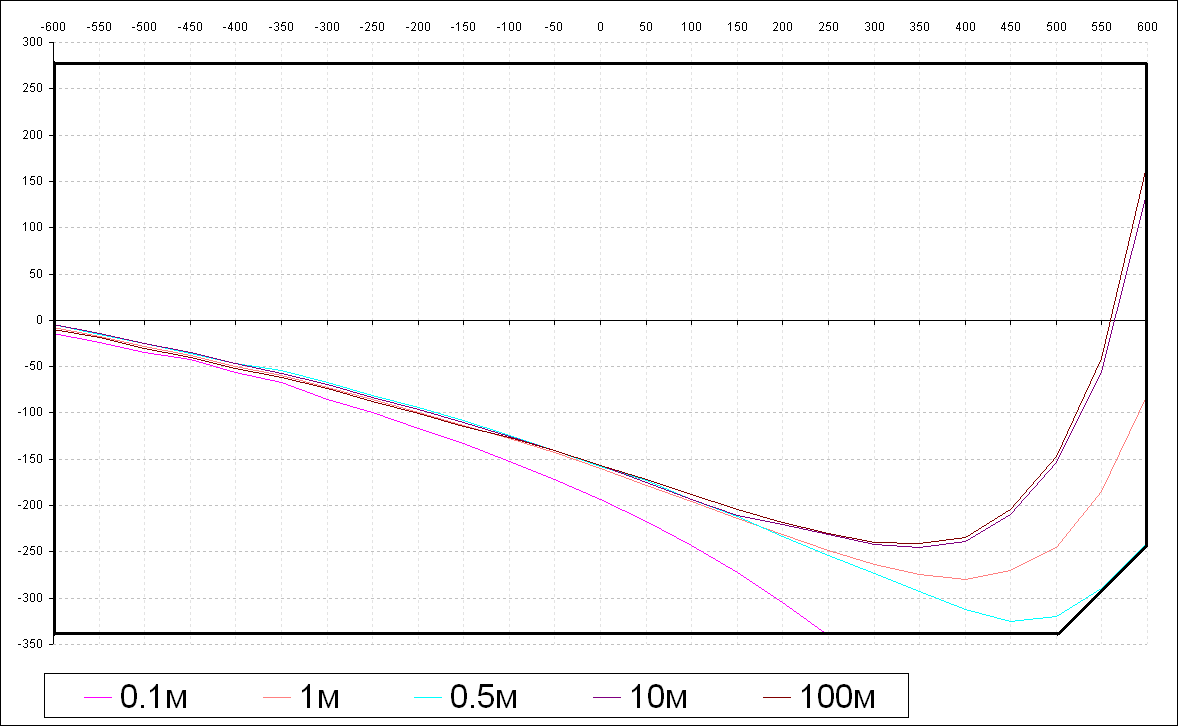 . 14. Z-F .Looking at the graphs, I want to give a lot of comments. At minimum zoom, focus values are slightly less than the “middle” (zero) for almost any distance. The pink curve for a distance of 10 cm ends at a zoom value of about 250, which corresponds to the minimum focus value. This curve has a decreasing character and is convex upward. The red curve for a distance of 1 m has a completely different shape. Firstly, it is not monotonous, and secondly, as regards the convexity property, there is an inflection point. The curves for distances of 10 m and 100 m are of a similar nature. The latter, by the way, practically coincide, which I already knew in advance. Therefore, the measured distances of 10 and 100 meters, of course, I took approximately. What sways the blue curve for a half meter distance - initially I was not going to take measurements on it.I selected this distance approximately based on the principle that as close as possible with a fragment of the corresponding curve approach the corner boundary of the region (cut). And so it happened: this border practically touches a fragment of the curve. In general, it is worth noting that the upper half of the region (positive focus values) is practically not used. The exception is at a great distance from the subject to the lens and at the largest zoom. And yet, for almost all distances (except the closest, less than half a meter), at low zoom (150 or less), the focus values are almost the same. Generally speaking, all the stated measurement facts should have a theoretical interpretation, based on the laws of optics. But at the current time, I have no idea about the devices of lenses of this kind. Maximum,what I encountered in the field of optics is the construction of a simple two-lens refractor telescope. And in the case of this camcorder - I did not understand the mechanics of optics. At the output, only two moving nodes are not available: the focus node (responsible for the focus) and the zoom node. And I don’t know how many total lenses are inside. I suppose two that are connected with these moving nodes. It is also worth noting that when adjusting the focus, the zoom also visually changes slightly, even if the corresponding node is fixed.connected to these moving nodes. It is also worth noting that when adjusting the focus, the zoom also visually changes slightly, even if the corresponding node is fixed.connected to these moving nodes. It is also worth noting that when adjusting the focus, the zoom also visually changes slightly, even if the corresponding node is fixed.At the end of the article, we move on to practical testing of the camcorder. I decided not to take a lot of still pictures, but immediately upload the whole video. I recorded video capture through the device, the sound was written separately to the audio recorder. The original resolution is 720 by 576. After uploading the video to YouTube, its quality has noticeably changed.When you turn on the camera, the first thing that happens is the initialization of the stepper motors of zoom and focus on the background of the video image. This image is black and white and without AGC, since the video processor initialization procedure has not yet passed. At the bottom left, the current date and time will display the date and time of compilation of the current camera firmware. In the firmware source code, I created the corresponding variables that are located at fixed addresses in the HEX code. It is assumed that at the compilation stage, more precisely after it, a program will be automatically executed that takes the values of the variables from the system time and inserts them into the HEX file at the desired addresses. In addition, there still need to recount the checksums. Perhaps there is a simpler way. In the example in the video, these variables are equal to zero, since I have not yet implemented this function.After the initialization of the SD, the video processor is initialized and a greeting is immediately displayed on the background of the video image. When adjusting the zoom and focus, their coordinates are displayed at the bottom right. In the video, I demonstrate the use of the function of saving and recalling templates (presets) of zoom and focus in various parts of the image. When clearing a preset, the corresponding variables acquire the value 0xFFFF, which corresponds to a value of -1. This function, in principle, is superfluous, it can be excluded.In the last section of the menu, which is used for debugging, I demonstrate the record of category 9 byte 3. The functions corresponding to this byte are in the previous section of the menu, I wrote about them many times. Due to the fact that the current state of the byte is not read from the video processor, I manually set it to “48” as one of the acceptable ones. After that, I change the individual bits of this byte, thereby showing the "Mirror" and "Inverse Burst" functions.When adjusting the “Burst” level in the penultimate section of the menu, you will notice a small firmware bug that is easy to fix. Of the other shortcomings - sometimes, when updating the time, gaps in the characters occur. I think this is due to the “crooked” installation of electronics inside the camcorder.In general, when operating the camera, minor inconveniences associated with menu navigation were found. Therefore, it is quite possible that the necessary revision will be made over time.Yes, I almost forgot. As promised, I bring two photographs of what the filling of the camcorder turned into after development.
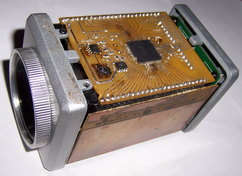 Fig. 15. An updated view of the camcorder inside the bottom.
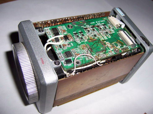 Fig. 16. An updated view of the camcorder inside the top.