To prevent a decrease in IQ during self-isolation, there was a desire to do something useful for themselves, and if you're lucky - not only. Cutting the nth circle around the apartment, my eyes caught on a car scanner, which I took from a friend for further study, namely Lexia 3, aka Actia XS Evolution. Here's one: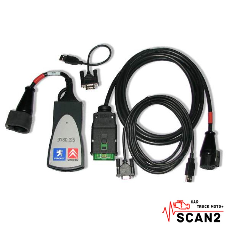 Its huge drawback was that only DiagBox software designed to diagnose Peugeout / Citroen cars can work with it. It was impossible to put up with the latter (s), therefore the idea arose that if this scanner was forced to send and receive arbitrary messages to the vehicle’s CAN bus, thereby turning it into a universal adapter.So, the action plan:
- Collect USB communication between the PC and our patient.
- Understand how communication occurs between the adapter driver and software.
- Repeat the exchange and feel good (spoiler: it turned out to be a bit more complicated).
1. Exchange
The DiagBox software complex freely surfs the Internet, so there were no difficulties with step 1, especially since it comes with a small utility for identifying the adapter, which somewhat simplified the task from step 2. When receiving an exchange via USB, a trial version of USBLyzer helped .We are going to success. In the picture, the sent data packet, the type of device in the dispatcher, and the same utility.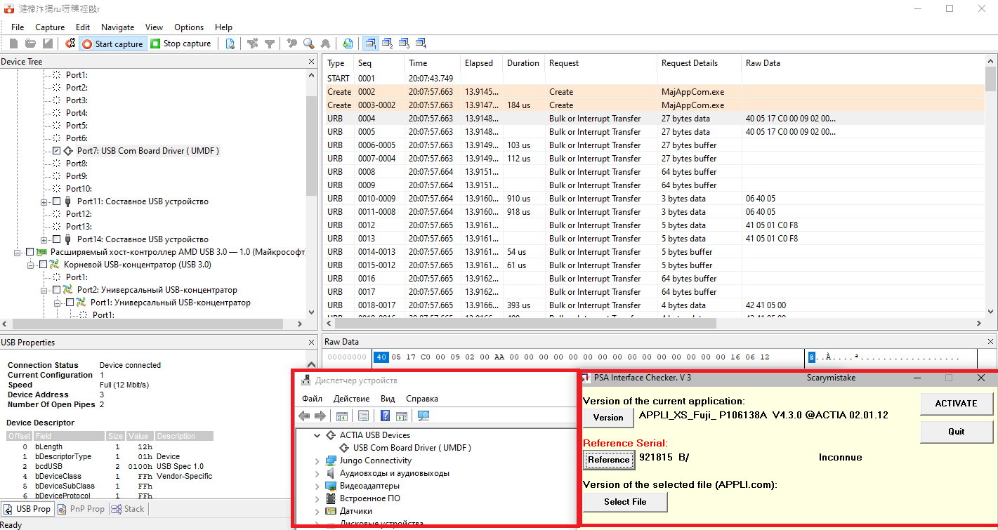 Looking at the IRPs when opening the device and exchanging with it, we can conclude that the work is done through the standard Windows I / O mechanism, namely, to open the device’s virtual file, the CreateFile function and for the exchange, DeviceIOControl.
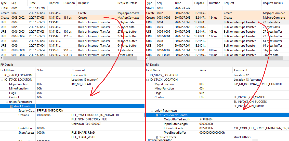
2. Debriefing
The data is collected, IOCTL ID and flags are received, it remains the case for small, open the file device and send a packet of bytes there. Just open it? Search through WinObj did not give any results, when connected, the adapter does not have an exact name, only an implicit link with a constantly changing ID, that is, simply opening a device like a COM port will not workCreateFile("\\\\.\\COM1", ...)
Studying the program files made it clear, everything turned out to be quite simple - the adapter has its own unique GUID, with the help of which the operating system is asked for a list of all devices with such a GUID and if they are present, we will get a link to the device, the\\?\USB#VID_103A&PID_F000#6&268bff9b&0&7#{75a835f4-d77d-4402-8585-c42247f25b76}\vcommusb0opening of which will be successful.Function returning the path instead of the GUID:CM_Get_Device_Interface_List(InterfaceClassGuid, pDeviceID, Buffer, BufferLen, ulFlags);
The "file" opens successfully, do not forget about the flags that were obtained via USBLyzerDevice = CreateFile(DeviceName, GENERIC_WRITE | GENERIC_READ, FILE_SHARE_WRITE | FILE_SHARE_READ, NULL, OPEN_EXISTING, 0, NULL);
3. Final
We send a packet of bytes, and in response - silence ...bStatus = DeviceIoControl(Device, 0x220003, send_buf, send_len, out_buf, max_out_len, &returned_len, NULL);
For a long time I sat and looked at the monitor, here is the same exchange, here are the responses from the device, here are the flags, exactly the same as I repeated, but nothing comes of it. Having finally lost all hope of success, I had one last thing - heavy artillery in the form of a disk from the Hacker magazine with the OllyDbg program. We start, attach to the process, put the breakpoint on the DeviceIoControl functions and what we see.
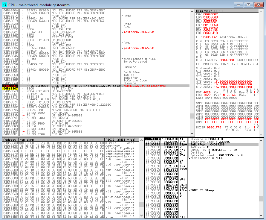 The king is not real. A completely different IOCTL code, the data is not at all like the one seen through USBLyzer.What was sent to the device:
<b>00 FA</b> <i>AA</i> BA 7C 15 00 00 00 00 00 00
And that went over USB:40 05 15 C0 <b>00 FA</b> 00 00 <i>AA</i> 00 00 00 00 00 00 00 00 00 00 00 00 00 00 00 41
The hint was in the name of the device visible in the task manager. I found an article on the Microsoft website about what a UMDF USB driver is. Clear block diagram: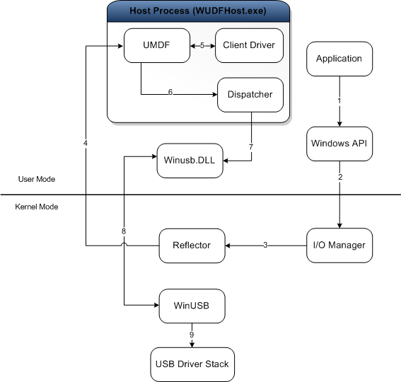 It turns out that what we see in USBLyzer is the transport layer of client data transfer, which is implemented in the UMDF driver (direction 7 in the picture), while we transfer data to the device (direction 2 in the picture), which will first go to the driver, and then go to the USB bus. I hope I clearly explained.Now it’s all clear where the other IOCTL IDs and data come from. Well, it’s even simpler, you don’t have to rack your brains on how to implement transport, we have the simplest request-response interface. Also in the program files the description of the exchange protocol (partial) was accidentally overloaded, it is a pity only in French.
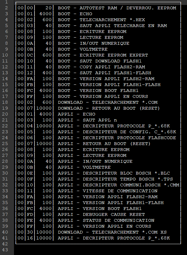 According to him, in the message above, the firmware version (00 FA) was requested, to which a response was received with the line APPLI_XS_Fuji_ P106138A V4.3.0 @ACTIA 02.01.12.ALL. We configure CAN, send request-response addresses for communication using the ISO-TP protocol and get a fully working adapter with the car. For ease of use, a wrapper was written that, as far as possible, complies with the PassThru J2534 standard, so that this adapter can be used with various automotive software, including its own design.Video of work (stdout is output to the console for debugging convenience):Sources can be found here