In the last article, we talked about dynamic QR codes that were recorded on VHS tapes. The PCM epidemic caught me too, so it's time to pick this format up.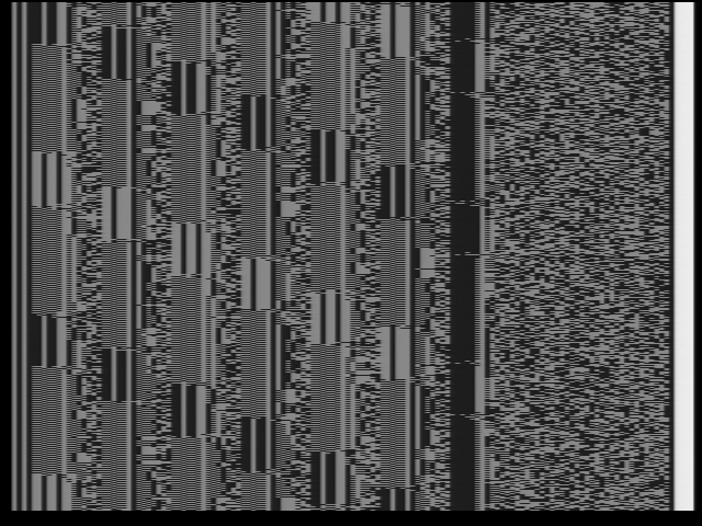 At the first stage, we will try to implement a software decoder. This is not the last article on this topic, since at Japanese auctions processors may end, and PCM should be in every home! Finding a video player is not a problem.To work, you need a file with the recording of these same QR codes. You can get it using the video capture card. Well, the signal source, of course. You can directly capture the processor output or record on a tape recorder. Ideally, work immediately with the capture device to decode the signal in real time.Any language will do. I started with Python. But it turned out to be rather slow on my laptop, so as a result I switched to C ++. By the way, independently of each other (almost) our small community is developing 3 decoder projects: on OpenCV (C ++), on Qt (C ++) and on LabView. The first one will be discussed. OpenCV was chosen due to the simplicity of working with both capture devices and pre-recorded videos. Plus, all manipulations with the image there are highly optimized.The first problem you will encounter is lost data. In any case, they will and cannot be avoided in any way without “specialized” equipment. PCM uses more lines than fit in the visible area of the frame. In the case of the NTSC region, this number is 492 lines per frame with a visible area of 480. In the case of PAL, everything is much sadder.
1. PCM NTSC 44,056 kHz, PAL 44,1 kHz.
2. VHS . ( ). , . , . , . .
There are two solutions to this problem. Work with the capture card in a tricky way bypassing the driver and take data from the ADC, after which they can be converted to a full PCM frame, or hammer on missing lines. The second option sounds a little wild, but the data storage format allows you to recover part of the data. In the case of the NTSC region, it turns out to meet the limitations of the error correction system.Due to the use of service lines, you cannot take a video card with a composite output and make the PCM processor play. Iron will ignore the entire frame if it does not find the title in a specific line. There are a couple of thoughts on this subject, but about this somehow later.To begin with, the video signal is interlaced. Each frame contains as it were two, composed of odd and even lines. They are called fields. It is with the fields that the PCM processor works. Therefore, we also need to split the original stream. Just before that, it would be nice to convert a black-and-white (grayscale) image to binary so that it would be easier to work.At this point we come across three difficulties associated with the features of video capture devices. You cannot use a static threshold for binarizing an image. But OpenCV itself solves this problem, with the help of which we get a quite decent result with one magic line.threshold(greyFrame, fullFrame, 0, 255, THRESH_BINARY + THRESH_OTSU);
The second problem is, suddenly, color. PCM processors do not use the color component of the video signal, but capture cards may try to extract it from the noise. This is especially noticeable on the cheapest EasyCAP. This can spoil the result of binarization a bit, so first you need to convert the image to shades of gray.cvtColor(srcFrame, greyFrame, CV_BGR2GRAY);
In addition to the above, EasyCAP manages to confuse the fields in places. More precisely, it skips the first line, because of which all other lines are not in place. For recording a matinee from kindergarten, this is not very important, but here it already becomes a problem. Arranging lines in the correct order is easy enough. At the end of each frame there is an area without data. If we move the lines containing the useful signal down to the stop, then the fields are guaranteed to return to their places. When studying, I tried to use three capture devices from different price ranges, but the most useful in the end turned out to be the cheapest, as it revealed a number of problems. Color spots and a higher level of brightness of data bits can be observed in the image when compared with the first illustration of an article captured on the Magewell Pro Capture AIO.It's time to remember what the signal is stored on. VHS tape recorders do not differ in special quality, as this is a household format. Frame and line sync pulses alone are not enough for stable operation. Therefore, additional synchronization marks are added to the video signal. In each line at the beginning there is a sequence of alternating two white and two black “pixels”, and at the end of the line there is a small area with maximum brightness, which adjusts the AGC. The data bits themselves have a brightness of 60% of the maximum for 1 and less than 20% for 0. Here is an example of why these labels are necessary: inversion of the picture from the cassettes at the beginning and end of the frame.
 According to the synchronization marks, in each row there is a data area. Next, you need to determine the bit width (only 128 bits per line) and shrink the image line to 16 bytes.Let's take a closer look at the data format. The line consists of 8 blocks of 14 bits each containing values for output to the DAC (samples) and error correction codes, and a block with a checksum (CRC-16 / CCITT-FALSE). By checksums, the dropped lines are determined, the data in which the device will try to recover. Each line contains three samples for the left and right channels, a parity block P (xor of all samples) and a mysterious Q. The order is as follows: L0, R0, L1, R1, L2, R2, P, Q. Today, Q correction is not possible we will, since this material is not yet fully understood and the implementation requires debugging.
 If you use "as is", then a broken line means the loss of three samples at once, which will be noticeable to the ear on a metal ring. But dida were smarter and decided to record data with ladders. Only one block is taken from one line. The next is taken with a slight offset. The step of the stairs takes 16 lines. Block L0 is taken from 1 line. Block R0 with line 17 ... Thus, using the parity block, you can recover data from 16 rows lost in a row. But only if there is one error inside the ladder. Block Q allows you to fix two errors, which restores up to 32 lost lines.
 Consider a simple example. There is a fragment of a PCM frame in which several lines are broken (highlighted in red). The first 4 ladders are processed normally. The fifth will capture the broken line. The Q block is lost first, but since it serves to correct errors, and the samples themselves are not damaged, you can go further. With the sixth ladder, we do the same. Then again there are undamaged ladders up to 21. Block P suffers in it. It also serves to restore data. You can skip. So we go to 37 stairs, where the sample of the right channel will be damaged. To restore it, you need to perform XOR for the parity block and all other samples:
As a result, we get the initial value. If there are two errors, an attempt is made to restore using the Q block. If there are more of them, then there is nothing to be done with this except to interpolate the values of the beaten samples or to reset them.The process of passing through the field can be observed on a small GIF animation. And so we go until the last step of the ladder rests against the end of the field. Hardware PCM has a circular buffer. As soon as the line has been processed, it can be filled with new data. Thus, the last step jumps up without interrupting playback.I chose a slightly different principle of work. Now there is no longer such a memory limit, so the buffer has a slightly larger size: the height of the field plus the height of the ladder. As soon as the ladder reaches the end of the buffer, the last 111 lines are transferred to the beginning, and filling with new data is already from 112 lines. Of course, we must not forget that when working with the capture card we lose some of the lines. Therefore, be sure to fill in the missing lines with zeros in order to mark them for further recovery by CRC errors.PCM was originally 14-bit. But over time, when VHS video recorders improved picture quality, manufacturers switched to 16 bits, without forgetting about backward compatibility.
3. 14- PCM 12 . ( ).
In the 16-bit PCM, there is no Q block at all, so there is a special mark in the field heading “Q correction is not possible”. Instead, 2 missing bits of samples and P were collected. In this case, the height of the ladder is not 8 steps, but only 7, since the missing bits of the block are stored on its own line, and not separately. Understanding how a 16-bit PCM works is quite simple using the example of capturing a meander with a frequency of 100 Hz and maximum amplitude. Everything immediately falls into place. Now it's time to save the result in a wav file. The libsndfile library will help in this. Although ... PCM does not save files, but immediately plays it. Here you can remember about such a cool thing, like pipe. When the output of one program is input to another. We simply specify stdout as the destination and redirect the stream to the ffplay program.
./ggg -i easycap.avi -o - | ffplay -
Now you can enjoy the drops and continue to debug the code to get rid of them ...That's all for today. You can download the decoder source from the page on GitHub: https://github.com/walhi/pcm . There is also a generator. Someday I will design it as a plugin for foobar ...Active work is underway to finish the recovery on the Q block, so for more or less correct work, you will have to jump over the commits. But these are trifles. Those who wish to play can download the capture example .