 In the previous part, we figured out how to display two-dimensional objects, such as a pixel and a line (segment), but you really want to quickly create something three-dimensional. In this article, for the first time, we will try to display a 3D object on the screen and get acquainted with new mathematical objects, such as a vector and a matrix, as well as some operations on them, but only those that are applicable in practice.In the second part we will consider:
- Coordinate systems
- Dot and vector
- The matrix
- Vertices and Indexes
- Visualization conveyor
Coordinate systems
It is worth noting that some examples and operations in the articles are presented inaccurately and greatly simplified to improve understanding of the material, grasping the essence, you can independently find the best solution or fix errors and inaccuracies in the demo code. Before we draw something three-dimensional, it is important to remember that all three-dimensional on the screen is displayed in two-dimensional pixels. In order for the objects drawn by pixels to look three-dimensional, we need to make out a little math. We will not consider formulas and objects without seeing their application. That is why, all the mathematical operations that you will encounter in this article will be put into practice, which will simplify their understanding. The first thing to understand is the coordinate system. Let's see which coordinate systems are used, and also choose which one to use for us.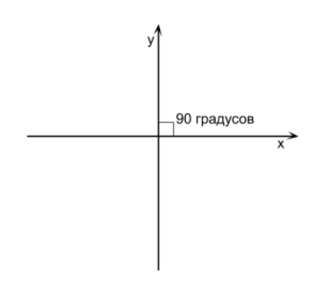 What is a coordinate system? This is a way to determine the position of a point or character in a game consisting of points using numbers. The coordinate system has 2 directions of the axes (we will denote them as X, Y) if we work with 2D graphics. If we set a 2D object with a larger Y and it becomes higher than it was before, this means that the Y axis is upward. If we give the object a larger X and it becomes more to the right, this means that the X axis is directed to the right. This is the direction of the axes, and together they are called the coordinate system. If an angle of 90 degrees is formed at the intersection of the X and Y axes, then such a coordinate system is called rectangular (also called a Cartesian coordinate system) (see Figure above).
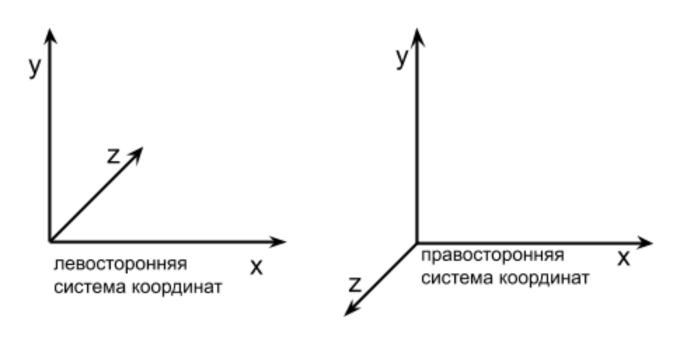
Dot and vector
Now you basically know what coordinate systems are and what axis directions are. Next, you need to parse what a point and a vector are, because we will need them in this article for practice. A point in 3D space is a location specified through [X, Y, Z]. For example, we want to place our character at the very origin (perhaps in the center of the window), then his position will be [0, 0, 0], or we can say that he is located at the point [0, 0, 0]. Now, we want to place the enemy to the left of the player 20 units (for example, pixels), which means that he will be located at the point [-20, 0, 0]. We will constantly work with points, so we will analyze them in more detail later. What is a vector? This is the direction. In 3D space, it is described, like a point, by 3 values [X, Y, Z]. For example, we need to move the character up 5 units every second, meaning we will change Y, adding 5 to it every second, but we will not touch X and Z, this movement can be written as a vector [0, 5, 0]. If our character constantly moves down by 2 units and to the right by 1, then the vector of his movement will look like this: [1, -2, 0]. We wrote -2 because Y down decreases.The vector has no position, and [X, Y, Z] indicate the direction. A vector can be added to a point in order to get a new point shifted by a vector. For example, I already mentioned above that if we want to move a 3D object (for example, a game character) every 5 units up, then the displacement vector will be like this: [0, 5, 0]. But how to use it to move? Suppose the character is at the point [5, 7, 0], and the displacement vector is [0, 5, 0]. If we add a vector to the point, we get a new player position. You can add a point with a vector, or a vector with a vector according to the following rule.An example of adding a point and a vector :[ 5, 7, 0 ] + [ 0, 5, 0 ] = [ 5 + 0, 7 + 5 , 0 + 0 ] = [5, 12, 0] - this is the new position of our character. As you can see, our character moved 5 units up, from here a new concept appears - the length of the vector. Each vector has it, except for the vector [0, 0, 0], which is called the zero vector, such a vector also has no direction. For the vector [0, 5, 0], the length is 5, because such a vector shifts the point 5 units up. The vector [0, 0, 10] has a length of 10 because it can shift the point by 10 along the Z axis. But the vector [12, 3, -4] doesn’t tell you what the length is, so we will use the formula for calculating the length of the vector. The question arises, why do we need the length of the vector? One application is to find out how far the character will move, or to compare the speeds of characters who have a longer displacement vector, that’s faster. Length is also used for some operations on vectors.The length of the vector can be calculated using the following formula from the first part (only Z was added):
Let's calculate the length of the vector using the formula above [6, 3, -8];
The length of the vector [6, 3, -8] is approximately 10.44.We already know what a point, a vector is, how to sum a point and a vector (or 2 vectors), and how to calculate the length of a vector. Let's add a vector class and implement summation and length calculation in it. I also want to pay attention to the fact that we will not create a class for a point, if we need a point, then we will use the vector class, because both the point and the vector store X, Y, Z, just for the point this position, and for the vector the direction.Add the vector class to the project from the previous article, you can add it below the Drawer class. I called Vector my class and added 3 properties X, Y, Z to it:class Vector {
x = 0;
y = 0;
z = 0;
constructor(x, y, z) {
this.x = x;
this.y = y;
this.z = z;
}
}
Note that the fields x, y, z without the functions of "accessors", so we can directly access the data in the object, this is done for faster access. Later, we will optimize this code even more, but for now, leave it so as to improve readability.Now we implement the summation of vectors. The function will take 2 summable vectors, so I am thinking of making it static. The body of the function will work according to the formula above. The result of our summation is a new vector, with which we will return:static add(v1, v2) {
return new Vector(
v1.x + v2.x,
v1.y + v2.y,
v1.z + v2.z,
);
}
It remains to implement the function of calculating the length of the vector. Again, we implement everything according to the formulas that were higher:getLength() {
return Math.sqrt(
this.x * this.x + this.y * this.y + this.z * this.z
);
}
Now let's look at another operation on the vector, which will be needed a little later in this and much in subsequent articles - “normalization of the vector”. Suppose we have a character in the game whom we move with the arrow keys. If we press up, then it moves to the vector [0, 1, 0], if down, then [0, -1, 0], to the left [-1, 0, 0] and to the right [1, 0, 0]. It can be clearly seen here that the lengths of each of the vectors are 1, that is, the character’s speed is 1. And let's add a diagonal movement, if the player clamps the arrow up and to the right, what will be the displacement vector? The most obvious option is the vector [1, 1, 0]. But if we calculate its length, we will see that it is approximately equal to 1.414. It turns out that our character will go faster diagonally? This option is not suitable, but for our character to go diagonally at a speed of 1, the vector should be:[0.707, 0.707, 0]. Where did I get such a vector? I took the vector [1, 1, 0] and normalized it, after which I got [0.707, 0.707, 0]. That is, normalization is the reduction of a vector to a length of 1 (unit length) without changing its direction. Note that the vectors [0.707, 0.707, 0] and [1, 1, 0] point in the same direction, that is, the character will in both cases move strictly up to the right, but the vector [0.707, 0.707, 0] is normalized and the speed of the character Now it will be equal to 1, which eliminates the bug with accelerated diagonal movement. It is always recommended to normalize the vector before any calculations in order to avoid various kinds of errors. Let's see how to normalize a vector. It is necessary to divide each of its components (X, Y, Z) by its length. The function of finding the length is already there, half the work is done,now we write the normalization function of the vector (inside the Vector class):normalize() {
const length = this.getLength();
this.x /= length;
this.y /= length;
this.z /= length;
return this;
}
The normalize method normalizes the vector and returns it (this), this is necessary so that in the future it would be possible to use normalize in expressions.Now that we know what normalization of a vector is, and we know that it is better to perform it before using the vector, the question arises. If the normalization of a vector is a reduction to a unit length, that is, the speed of movement of an object (character) will be equal to 1, then how to speed up the character? For example, when moving a character diagonally up / right at a speed of 1, his vector will be [0.707, 0.707, 0], and what vector will be if we want to move the character 6 times faster? To do this, there is an operation called "multiplying a vector by a scalar." The scalar is the usual number by which the vector is multiplied. If the scalar is equal to 6, then the vector will become 6 times longer, and our character is 6 times faster, respectively. How to do scalar multiplication? For this, it is necessary to multiply each component of the vector by a scalar. For example, we solve the problem above,when the character moving to the vector [0.707, 0.707, 0] (speed 1) needs to be accelerated 6 times, that is, multiply the vector by scalar 6. The formula for multiplying the vector “V” by scalar “s” is as follows:
In our case, it will be:- a new displacement vector whose length is 6.It is important to know that a positive scalar scales a vector without changing its direction; if a scalar is negative, it also scales a vector (increases its length) but in addition changes the direction of the vector to the opposite.Let's implement the function of multiplyByScalarmultiplying a vector by a scalar in our Vector class:multiplyByScalar(s) {
this.x *= s;
this.y *= s;
this.z *= s;
return this;
}
The matrix
We figured out a bit with vectors and some operations on them that will be needed in this article. Next, you need to deal with matrices.We can say that a matrix is the most common two-dimensional array. It's just that in programming they use the term “two-dimensional array”, and in mathematics they use the “matrix”. Why are matrices needed in 3D programming? We will analyze this as soon as we learn to work with them a little. We will use only numerical matrices (an array of numbers). Each matrix has its own size (like any 2-dimensional array). Here are some examples of matrices:Of all operations on matrices, we now consider only multiplication (the rest later). It turns out that matrix multiplication is not the easiest operation, it can easily confuse if you do not carefully follow the order of multiplication. But don’t worry, you will succeed, because here we will only multiply and summarize. To begin with, we need to remember a couple of multiplication features that we need:- If we try to multiply the number A by the number B, then this is the same as B * A. If we rearrange the operands and the result does not change under any action, then they say that the operation is commutative. Example: a + b = b + a the operation is commutative, a - b ≠ b - a the operation is non-commutative, a * b = b * a the operation of multiplying numbers is commutative. So, the operation of matrix multiplication is non-commutative, in contrast to the multiplication of numbers. That is, multiplying the matrix M by the matrix N will not equal the multiplication of the matrix N by M.
- Matrix multiplication is possible if the number of columns of the first matrix (which is on the left) is equal to the number of rows in the second matrix (which is on the right).
Now we’ll take a look at the second feature of matrix multiplication (when multiplication is possible). Here are a few examples that demonstrate when multiplication is possible and when not:I think these examples clarified the picture a little when multiplication is possible. The result of matrix multiplication will always be a matrix, the number of rows of which will be equal to the number of rows of the 1st matrix, and the number of columns is equal to the number of columns of the 2nd. For example, if we multiply matrix 2 by 6 and 6 by 8, we get a matrix of size 2 by 8. Now we go directly to the multiplication itself.For multiplication, it is important to remember that the columns and rows in the matrix are numbered starting from 1, and in the array from 0. The first index in the matrix element indicates the row number, and the second the column number. That is, if the matrix element (array element) is written as: m28, this means that we turn to the second row and eighth column. But since we will work with arrays in the code, all indexing of rows and columns will start at 0.Let's try to multiply 2 matrices A and B with specific sizes and elements:
It can be seen that the matrix A has a size of 3 by 2, and the matrix B has a size of 2 by 2, multiplication is possible:
As you can see, we have a 3 by 2 matrix, the multiplication is initially confusing, but if there is a goal to learn how to multiply “without stress”, several examples need to be solved. Here is another example of multiplying the matrices A and B:
If multiplication is not completely clear, then it’s okay, because we do not have to multiply by leaf. We will write once the matrix multiplication function and we will use it. In general, all these functions are already written, but we do everything on our own.Now some more terms that will be used in the future:- A square matrix is a matrix in which the number of rows is equal to the number of columns, here is an example of square matrices:
- The main diagonal of a square matrix is called all the elements of the matrix whose row number is equal to the column number. Examples of diagonals (in this example, the main diagonal is filled with nines):
- A unit matrix is a square matrix in which all elements of the main diagonal are 1 and all the others are 0. Examples of unit matrices:
It is also important to remember this property that if we multiply any matrix M by a unit matrix that is suitable in size, for example, call it I, we get the original matrix M, for example: M * I = M or I * M = M. That is, multiplying the matrix by the identity matrix does not affect the result. We will return to the identity matrix later. In 3D programming, we will often use a 4 by 4 square matrix.Now let’s take a look at why we will need matrices and why multiply them? In 3D programming, there are many different 4 by 4 matrices that, if multiplied by a vector or point, will perform the actions we need. For example, we need to rotate the character in three-dimensional space around the X axis, how to do this? Multiply the vector by a special matrix, which is responsible for rotation around the X axis. If you need to move and rotate a point around the origin, then you need to multiply this point by a special matrix. Matrices have an excellent property - combining transformations (we will consider in this article). Suppose we need a character consisting of 100 points (vertices, but this will also be a little lower) in the application, increase 5 times, then rotate 90 degrees X, then move it up 30 units.As already mentioned, for different actions there are already special matrices that we will consider. To accomplish the task above, we, for example, loop through all 100 points and each first we multiply by the 1st matrix to increase the character, then we multiply by the 2nd matrix to rotate 90 degrees in X, then we multiply by 3 th to move 30 units up. In total, for each point we have 3 matrix multiplications, and 100 points, which means there will be 300 multiplications. But if we take and multiply the matrices among ourselves to increase by 5 times, rotate 90 degrees along X and move by 30 units. up, we get a matrix that contains all these actions. Multiplying a point by such a matrix, the point will be where it is needed. Now let's calculate how many actions are performed: 2 multiplications for 3 matrices, and 100 multiplications for 100 points,a total of 102 multiplications is definitely better than 300 multiplications before that. The moment when we multiplied 3 matrices to combine different actions into one matrix - is called a combination of transformations and we will certainly do it with an example.How to multiply the matrix by the matrix, we examined, but the paragraph read above speaks of the multiplication of the matrix by a point or vector. To multiply a point or vector, it is enough to represent them as a matrix.For example, we have a vector [10, 2, 5] and there is a matrix:
It can be seen that the vector can be represented by a matrix of 1 by 3 or by a matrix of 3 by 1. Therefore, we can multiply the vector by a matrix of 2 ways:As you can see, we can represent the vector as a row vector and multiply it by a matrix, or represent the vector as a column vector and multiply the matrix by it. Let's check if the result of the multiplication will be the same in both cases:Multiply the row vector by the matrix:
Now, multiply the matrix by the column vector:
We see that multiplying the row vector by the matrix and the matrix by the column vector, we got completely different results (we recall the commutativity). Therefore, in 3D programming, there are matrices that are designed to be multiplied only by a row vector, or only by a column vector. If we multiply the matrix intended for the row vector by the column vector, we get a result that will not give us anything. Use the vector / point representation convenient for you (row or column), only in the future, use the appropriate matrices for your vector / point representation. Direct3D, for example, uses a string representation of vectors, and all matrices in Direct3D are designed to multiply a row vector by a matrix. OpenGL uses a representation of a vector (or point) as a column,and all matrices are designed to multiply the matrix by a column vector. In the articles we will use the column vector and we will multiply the matrix by the column vector.To summarize what we read about the matrix.- To perform an action on a vector (or point), there are special matrices, some of which we will see in this article.
- To combine the transformation (displacement, rotation, etc.), we can multiply the matrices of each transformation with each other and get a matrix that contains all the transformations together.
- In 3D programming, we will constantly use 4 by 4 square matrices.
- We can multiply the matrix by a vector (or point) by representing it as a column or row. But for the column vector and row vector, you need to use different matrices.
After a little analysis of the matrices, let's add a 4 by 4 matrix class and implement methods for multiplying the matrix by the matrix, and the vector by the matrix. We will use the size of the matrix 4 by 4, because all standard matrices that are used for various actions (movement, rotation, scale, ...) are of such a size, we do not need matrices of a different size. Let's add the Matrix class to the project. Still sometimes the class for working with 4 by 4 matrices is called Matrix4, and this 4 in the title tells us about the size of the matrix (they also say the 4th order matrix). All matrix data will be stored in a 4 by 4 two-dimensional array.We turn to the implementation of multiplication operations. I do not recommend using loops for this. To improve performance, we all have to multiply line by line - this will happen due to the fact that all multiplications will occur with matrices of a fixed size. I will use cycles for the operation of multiplication, only to save the amount of code, you can write all the multiplication without cycles at all. My multiplication code looks like this:class Matrix {
static multiply(a, b) {
const m = [
[0, 0, 0, 0],
[0, 0, 0, 0],
[0, 0, 0, 0],
[0, 0, 0, 0],
];
for (let i = 0; i < 4; i++) {
for (let j = 0; j < 4; j++) {
m[i][j] = a[i][0] * b[0][j] +
a[i][1] * b[1][j] +
a[i][2] * b[2][j] +
a[i][3] * b[3][j];
}
}
return m;
}
}
As you can see, the method takes the matrices a and b, multiplies them and returns the result in the same array 4 by 4. At the beginning of the method I created a matrix m filled with zeros, but this is not necessary, so I wanted to show what dimension the result will be, you You can create a 4 by 4 array without any data.Now you need to implement the multiplication of the matrix by the column vector, as discussed above. But if you represent the vector as a column, you get a matrix of the form:by which we will need to multiply by 4 by 4 matrices to perform various actions. But in this example it is clearly seen that such a multiplication cannot be performed, because the column vector has 3 rows, and the matrix has 4 columns. What then to do? Some fourth element is needed, then the vector will have 4 rows, which will be equal to the number of columns in the matrix. Let's add such a 4th parameter to the vector and call it W, now we have all the 3D vectors in the form [X, Y, Z, W] and these vectors can already be multiplied by 4 by 4. In fact, the W component a deeper purpose, but we will get to know him in the next part (it's not for nothing that we have a 4 by 4 matrix, not 3 by 3 matrix). Add to the Vector class, which we created above the w component. Now the beginning of the Vector class looks like this:class Vector {
x = 0;
y = 0;
z = 0;
w = 1;
constructor(x, y, z, w = 1) {
this.x = x;
this.y = y;
this.z = z;
this.w = w;
}
I initialized W to one, but why 1? If we look at how the components of the matrix and vector are multiplied (the code example below), you can see that if you set W to 0 or any other value other than 1, then when multiplying this W will affect the result, but we don’t we know how to use it, and if we make it 1, then it will be in the vector, but the result will not change in any way. Now back to the matrix and implement in the Matrix class (you can also in the Vector class, there is no difference) the matrix is multiplied by a vector, which is already possible, thanks to W:static multiplyVector(m, v) {
return new Vector(
m[0][0] * v.x + m[0][1] * v.y + m[0][2] * v.z + m[0][3] * v.w,
m[1][0] * v.x + m[1][1] * v.y + m[1][2] * v.z + m[1][3] * v.w,
m[2][0] * v.x + m[2][1] * v.y + m[2][2] * v.z + m[2][3] * v.w,
m[3][0] * v.x + m[3][1] * v.y + m[3][2] * v.z + m[3][3] * v.w,
)
}
Please note that we presented the matrix as a 4 by 4 array, and the vector as an object with the properties x, y, z, w, in the future we will change the vector and it will also be represented by a 1 by 4 array, because it will speed up the multiplication. But now, in order to better see how multiplication occurs and improve understanding of the code, we will not change the vector.We wrote the code for matrix multiplication among ourselves and matrix-vector multiplication, but it is still not clear how this will help us in three-dimensional graphics.I also want to remind you that I call a vector both a point (position in space) and a direction, because both objects contain the same data structure x, y, z and the newly introduced w. Let's look at some of the matrices that perform basic operations on vectors. The first of these matrices will be the translation matrix. Multiplying the displacement matrix by a vector (location), it will shift by the specified number of units in space. And here is the displacement matrix:
Where dx, dy, dz mean displacements along the x, y, z axes, respectively, this matrix is designed to be multiplied by a column vector. Such matrices can be found on the Internet or in any literature on 3D programming, we do not need to create them ourselves, take them now, as the formulas that you use from school that you just need to know or understand why to use them. Let's check if, indeed, multiplying such a matrix by a vector, an offset will occur. Take as a vector we are going to move the vector [10, 10, 10, 1] (we always leave the 4th parameter W always 1), suppose that this is the position of our character in the game and we want to shift it 10 units up, 5 units to the right, and 1 unit away from the screen. Then the displacement vector will be like this [10, 5, -1] (-1 because we have a right-handed coordinate system and the further Z,the smaller it is). If we calculate the result without matrices, by the usual summation of vectors. That will result in the following result: [10 + 10, 10 + 5, 10 + -1, 1] = [20, 15, 9, 1] - these are the new coordinates of our character. Multiplying the matrix above by the initial coordinates [10, 10, 10, 1], we should get the same result, let's check this in the code, write the multiplication after the classes Drawer, Vector and Matrix:const translationMatrix = [
[1, 0, 0, 10],
[0, 1, 0, 5],
[0, 0, 1, -1],
[0, 0, 0, 1],
]
const characterPosition = new Vector(10, 10, 10)
const newCharacterPosition = Matrix.multiplyVector(
translationMatrix, characterPosition
)
console.log(newCharacterPosition)
In this example, we substituted the desired character offset (translationMatrix) into the displacement matrix, initialized its initial position (characterPosition) and then multiplied it with the matrix, and the result was output via console.log (this is debug output in JS). If you use non-JS, then output X, Y, Z yourself using the tools of your language. The result that we got in the console: [20, 15, 9, 1], everything agrees with the result that we calculated above. You may have a question, why get the same result by multiplying the vector by a special matrix, if we obtained it much easier by summing the vector with an offset component-wise. The answer is not the simplest and we will discuss it in more detail, but now it can be noted that, as discussed earlier, we can combine matrices with different transformations among themselves,thus cutting back on so many calculations. In the example above, we created the translationMatrix matrix manually and substituted the necessary offset there, but since we will often use this and other matrices, let's put it into a method in the Matrix class and pass the offset to it with arguments:static getTranslation(dx, dy, dz) {
return [
[1, 0, 0, dx],
[0, 1, 0, dy],
[0, 0, 1, dz],
[0, 0, 0, 1],
]
}
Take a closer look at the displacement matrix, you will see that dx, dy, dz are in the last column and if we look at the code for multiplying the matrix by a vector, we will notice that this column is multiplied by the W component of the vector. And if it were, for example, 0, then dx, dy, dz, we would multiply by 0 and the move would not work. But we can do W equal to 0 if we want to store the direction in the Vector class, because it’s impossible to move the direction, so we would protect ourselves, and even if we multiply such a direction by the displacement matrix, this will not break the direction vector, because all movement will be multiplied by 0.Total we can apply such a rule, we create a location like this:new Vector(x, y, z, 1)
And we’ll create the direction like this:new Vector(x, y, z, 0)
So we can distinguish between location and direction, and when we multiply the direction by the displacement matrix, we do not accidentally break the direction vector.Vertices and Indexes
Before we see what other matrices are, we’ll look a bit at how to apply our existing knowledge to display something three-dimensional on the screen. All that we deduced before this is lines and pixels. But let's now use these tools to derive, for example, a cube. In order to do this, we need to figure out what a three-dimensional model consists of. The most basic component of any 3D model is the points (we will call the vertices below) along which we can draw it; these are, in fact, a lot of location vectors, which, if we connect them correctly with lines, we get a 3D model (model grid ) on the screen, it will be without texture and without many other properties, but everything has its time. Take a look at the cube we want to output and try to understand how many vertices it has:
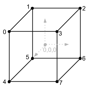
const vertices = [
new Vector(-1, 1, 1),
new Vector(-1, 1, -1),
new Vector(1, 1, -1),
new Vector(1, 1, 1),
new Vector(-1, -1, 1),
new Vector(-1, -1, -1),
new Vector(1, -1, -1),
new Vector(1, -1, 1),
];
I put each vertex in an instance of the Vector class, this is not the best option for performance (better in an array), but now our goal is to figure out how everything works.Let’s now take the coordinates of the vertices of the cube as pixels that we will draw on the screen, in this case we see that the size of the cube is 2 by 2 by 2 pixels. We created such a small cube so that look at the work of the scaling matrix, with which we will increase it. In the future, it is very good practice to make models small, even smaller than ours, in order to increase them to the desired size with not very different scalars.It’s just that drawing the cube points with pixels is not very clear, because all that we will see is 8 pixels, one for each vertex, it is much better to draw a cube with lines using the drawLine function from the previous article. But for this we need to understand from which vertices to which lines we pass. Take a look at the image of the cube with the indices again and we will see that it consists of 12 lines (or edges). It is also very easy to see that we know the coordinates of the beginning and end of each line. For example, one of the lines (upper near) should be drawn from vertex 0 to vertex 3, or from coordinates [-1, 1, 1] to coordinates [1, 1, 1]. We will have to write information about each line in the code manually looking at the image of the cube, but how to do it right? If we have 12 lines and each line has a beginning and an end, i.e. 2 points, then,to draw a cube we need 24 points? This is the correct answer, but let's take a look at the image of the cube again and pay attention to the fact that each line of the cube has common vertices, for example, at vertex 0 3 lines are connected, and so with each vertex. We can save memory and not write down the coordinates of the beginning and end of each line, just create an array and specify the vertex indices from the vertices array in which these lines begin and end. Let's create such an array and describe it only with vertex indices, 2 indexes per line (the beginning of the line and the end). And a little further, when we draw these lines, we can easily get their coordinates from the vertices array. My array of lines (I called it edges, because these are the edges of the cube) I created an array of vertices below and it looks like this:but let's take a look at the image of the cube again and pay attention to the fact that each line of the cube has common vertices, for example, at vertex 0 3 lines are connected, and so with each vertex. We can save memory and not write down the coordinates of the beginning and end of each line, just create an array and specify the vertex indices from the vertices array in which these lines begin and end. Let's create such an array and describe it only with vertex indices, 2 indexes per line (the beginning of the line and the end). And a little further, when we draw these lines, we can easily get their coordinates from the vertices array. My array of lines (I called it edges, because these are the edges of the cube) I created an array of vertices below and it looks like this:but let's look at the image of the cube again and pay attention to the fact that each line of the cube has common vertices, for example, at vertex 0 3 lines are connected, and so with each vertex. We can save memory and not write down the coordinates of the beginning and end of each line, just create an array and specify the vertex indices from the vertices array in which these lines begin and end. Let's create such an array and describe it only with vertex indices, 2 indexes per line (the beginning of the line and the end). And a little further, when we draw these lines, we can easily get their coordinates from the vertices array. My array of lines (I called it edges, because these are the edges of the cube) I created an array of vertices below and it looks like this:and so with each vertex. We can save memory and not write down the coordinates of the beginning and end of each line, just create an array and specify the vertex indices from the vertices array in which these lines begin and end. Let's create such an array and describe it only with vertex indices, 2 indexes per line (the beginning of the line and the end). And a little further, when we draw these lines, we can easily get their coordinates from the vertices array. My array of lines (I called it edges, because these are the edges of the cube) I created an array of vertices below and it looks like this:and so with each vertex. We can save memory and not write down the coordinates of the beginning and end of each line, just create an array and specify the vertex indices from the vertices array in which these lines begin and end. Let's create such an array and describe it only with vertex indices, 2 indexes per line (the beginning of the line and the end). And a little further, when we draw these lines, we can easily get their coordinates from the vertices array. My array of lines (I called it edges, because these are the edges of the cube) I created an array of vertices below and it looks like this:2 indexes per line (beginning of line and end). And a little further, when we draw these lines, we can easily get their coordinates from the vertices array. My array of lines (I called it edges, because these are the edges of the cube) I created an array of vertices below and it looks like this:2 indexes on each line (the beginning of the line and the end). And a little further, when we draw these lines, we can easily get their coordinates from the vertices array. My array of lines (I called it edges, because these are the edges of the cube) I created an array of vertices below and it looks like this:
const edges = [
[0, 1],
[1, 2],
[2, 3],
[3, 0],
[0, 4],
[1, 5],
[2, 6],
[3, 7],
[4, 5],
[5, 6],
[6, 7],
[7, 4],
];
There are 12 pairs of indices in this array, 2 vertex indices per line.Let's get acquainted with another matrix that will increase our cube, and finally, try to draw it on the screen. The Scale Matrix looks like this:
Parameters sx, sy, sz on the main diagonal mean how many times we want to increase the object. If we substitute 10, 10, 10 into the matrix instead of sx, sy, sz, and multiply this matrix by the vertices of the cube, this will make our cube ten times larger and it will no longer be 2 by 2 by 2, but 20 by 20 by 20.For the scaling matrix, as well as for the displacement matrix, we implement the method in the Matrix class, which will return the matrix with the arguments already substituted:static getScale(sx, sy, sz) {
return [
[sx, 0, 0, 0],
[0, sy, 0, 0],
[0, 0, sz, 0],
[0, 0, 0, 1],
]
}
Visualization conveyor
If we now try to draw a cube with lines using the current coordinates of the vertices, we will get a very small two-pixel cube in the upper left corner of the screen, because the origin of the canvas is there. Let's cycle through all the vertices of the cube and multiply them by the scaling matrix to make the cube bigger, and then by the displacement matrix to see the cube not in the upper left corner, but in the middle of the screen, I have the code for enumerating vertices with matrix multiplication below array of edges, and looks like this:const sceneVertices = []
for(let i = 0 ; i < vertices.length ; i++) {
let vertex = Matrix.multiplyVector(
Matrix.getScale(100, 100, 100),
vertices[i]
);
vertex = Matrix.multiplyVector(
Matrix.getTranslation(400, -300, 0),
vertex
);
sceneVertices.push(vertex);
}
Please note that we do not change the original vertices of the cube, but save the result of multiplication into the sceneVertices array, because we may want to draw several cubes of different sizes in different coordinates, and if we change the initial coordinates, then we won’t be able to draw the next cube, t .to. there’s nothing to start from, the initial coordinates will be corrupted by the first cube. In the code above, I increased the original cube by 100 times in all directions, thanks to multiplying all the vertices by the scaling matrix with arguments 100, 100, 100, and I also moved all the vertices of the cube to the right and lower by 400 and -300 pixels, respectively, since we have the canvas sizes from the previous article are 800 by 600, it will just be half the width and height of the drawing area, in other words, the center.We have finished with the vertices so far, but still need to draw all this using drawLine and the edges array, let's write another loop below the vertices loop to iterate over the edges and draw all the lines in it:drawer.clearSurface()
for (let i = 0, l = edges.length ; i < l ; i++) {
const e = edges[i]
drawer.drawLine(
sceneVertices[e[0]].x,
sceneVertices[e[0]].y,
sceneVertices[e[1]].x,
sceneVertices[e[1]].y,
0, 0, 255
)
}
ctx.putImageData(imageData, 0, 0)
Recall that in the last article we start all drawing by clearing the screen from the previous state by calling the clearSurface method, then I iterate over all the faces of the cube and draw the cube with blue lines (0, 0, 255), and I take the coordinates of the lines from the sceneVertices array, t .to. there are already scaled and moved vertices in the previous cycle, but the indices of these vertices coincide with the indices of the original vertices from the vertices array, because I processed them and put them into the sceneVertices array without changing the order. If we run the code now, we will not see anything on the screen. This is because in our coordinate system, Y looks up, and in the coordinate system, canvas looks down. It turns out that there is our cube, but it is outside the screen and to fix this, we need to flip the picture in Y (mirror) before drawing a pixel in the Drawer class. So far, this option will be enough for us, as a result, the code for drawing a pixel for me looks like this:drawPixel(x, y, r, g, b) {
const offset = (this.width * -y + x) * 4;
if (x >= 0 && x < this.width && -y >= 0 && y < this.height) {
this.surface[offset] = r;
this.surface[offset + 1] = g;
this.surface[offset + 2] = b;
this.surface[offset + 3] = 255;
}
}
It can be seen that in the formula for obtaining offset, Y is now with a minus sign and the axis now looks in the direction we need, also in this method I added a check for going beyond the limits of the pixel array. Some other optimizations appeared in the Drawer class due to the comments on the previous article, so I post the entire Drawer class with a few optimizations and you can replace the old Drawer with this one:Improved Drawer Class Codeclass Drawer {
surface = null;
width = 0;
height = 0;
constructor(surface, width, height) {
this.surface = surface;
this.width = width;
this.height = height;
}
drawPixel(x, y, r, g, b) {
const offset = (this.width * -y + x) * 4;
if (x >= 0 && x < this.width && -y >= 0 && y < this.height) {
this.surface[offset] = r;
this.surface[offset + 1] = g;
this.surface[offset + 2] = b;
this.surface[offset + 3] = 255;
}
}
drawLine(x1, y1, x2, y2, r = 0, g = 0, b = 0) {
const round = Math.trunc;
x1 = round(x1);
y1 = round(y1);
x2 = round(x2);
y2 = round(y2);
const c1 = y2 - y1;
const c2 = x2 - x1;
const length = Math.max(
Math.abs(c1),
Math.abs(c2)
);
const xStep = c2 / length;
const yStep = c1 / length;
for (let i = 0 ; i <= length ; i++) {
this.drawPixel(
Math.trunc(x1 + xStep * i),
Math.trunc(y1 + yStep * i),
r, g, b,
);
}
}
clearSurface() {
const surfaceSize = this.width * this.height * 4;
for (let i = 0; i < surfaceSize; i++) {
this.surface[i] = 0;
}
}
}
const drawer = new Drawer(
imageData.data,
imageData.width,
imageData.height
);
If you run the code now, then the following image will appear on the screen:Here you can see that there is a square in the center, although we expected to get a cube, what's the matter? In fact - this is the cube, it just stands perfectly perfectly aligned with one of the faces (side) towards us, so we do not see the rest of it. Also, we have not yet become familiar with projections, and therefore the back face of the cube does not become smaller with distance, as in real life. In order to make sure that this is really a cube, let's rotate it a bit so that it looks like the image we saw earlier when we made up the vertex array. In order to rotate the 3D image, you can use 3 special matrices, because we can rotate around one of the axes X, Y or Z, which means that for each axis there will be its own rotation matrix (there are other ways of rotation, but this is the topic of the next articles). Here's what these matrices look like:If we multiply the vertices of the cube by one of these matrices, then the cube will rotate by the specified angle (a) around the axis, the rotation matrix around which we will choose. There are some features when turning around several axes at once, and we will look at them below. As you can see from the matrix example, they use 2 functions sin and cos, and JavaScript already has a functional for calculating Math.sin (a) and Math.cos (a), but they work with radian measure of angles, which may not seem the most convenient if we want to rotate the model. For example, it’s much more convenient for me to turn something 90 degrees (degree measure), which in a radian measure will meanPi / 2(There is also an approximate Pi value in JS, this is the constant Math.PI). Let's add 3 methods to the Matrix class to get rotation matrices, with an accepted rotation angle in degrees, which we will convert to radians, because they are needed for the sin / cos functions to work:static getRotationX(angle) {
const rad = Math.PI / 180 * angle;
return [
[1, 0, 0, 0],
[0, Math.cos(rad), -Math.sin(rad), 0],
[0, Math.sin(rad), Math.cos(rad), 0],
[0, 0, 0, 1],
];
}
static getRotationY(angle) {
const rad = Math.PI / 180 * angle;
return [
[Math.cos(rad), 0, Math.sin(rad), 0],
[0, 1, 0, 0],
[-Math.sin(rad), 0, Math.cos(rad), 0],
[0, 0, 0, 1],
];
}
static getRotationZ(angle) {
const rad = Math.PI / 180 * angle;
return [
[Math.cos(rad), -Math.sin(rad), 0, 0],
[Math.sin(rad), Math.cos(rad), 0, 0],
[0, 0, 1, 0],
[0, 0, 0, 1],
];
}
All 3 methods begin with converting degrees to radians, after which we substitute the angle of rotation in radians into the rotation matrix, passing the angles into the functions sin and cos. Why the matrix is such, you can read more on the hub in the thematic articles, with a very detailed explanation, otherwise you can perceive these matrices as formulas that have been calculated for us and we can be sure that they are working.Above in the code, we implemented 2 cycles, the first one converts vertices, the second one draws lines by vertex indices, as a result, we get a picture from the vertices on the screen, and let's call this section of code the visualization pipeline. The conveyor because we take the peak and in turn do different operations with it, scale, shift, rotation, rendering, as on a normal industrial conveyor. Now let's add to the first cycle in the visualization pipeline, in addition to scaling, rotation around the axes. First, I will turn around X, then around Y, then increase the model and move it (the last 2 actions are already there), so the whole loop code will be like this:for(let i = 0 ; i < vertices.length ; i++) {
let vertex = Matrix.multiplyVector(
Matrix.getRotationX(20),
vertices[i]
);
vertex = Matrix.multiplyVector(
Matrix.getRotationY(20),
vertex
);
vertex = Matrix.multiplyVector(
Matrix.getScale(100, 100, 100),
vertex
);
vertex = Matrix.multiplyVector(
Matrix.getTranslation(400, -300, 0),
vertex
);
sceneVertices.push(vertex);
}
In this example, I rotated all the vertices around the X axis by 20 degrees, then around Y by 20 degrees and I already had 2 remaining transformations. If you did everything correctly, then your cube should now look three-dimensional:Turning around the axes has one feature, for example, if you turn the cube first around the Y axis, and then around the X axis, then the results will differ:There are other features, for example, if you turn the cube 90 degrees on the X axis, then 90 degrees on the Y axis, and finally 90 degrees around the Z axis, then the last rotation around Z will cancel the rotation around X, and you get the same the result is as if you just rotated the figure 90 degrees around the Y axis. To see why this happens, take any rectangular (or cubic) object in your hands (e.g. assembled Rubik's cube), remember the initial position of the object and rotate it 90 degrees first around imaginary X, and then 90 degrees around Y and 90 degrees around Z and remember which side it has become towards you, then start from the initial position you remembered earlier and do the same, removing the turns of X and Z, turn only around Y - you will see that the result is the same.Now we will not solve this problem and go into its details, this rotation is currently completely satisfactory to us, but we will mention this problem in the third part (if you want to understand more now, try searching for articles on the hub by the query “hinged lock”) .Now let's optimize our code a bit, it was mentioned above that matrix transformations can be combined with each other by multiplying transformation matrices. Let's try not to multiply each vector first by the rotation matrix around X, then around Y, then scaling and at the end of the move, and first, before the loop, we multiply all the matrices, and in the loop we will multiply each vertex by only one resulting matrix, I have the code came out like this:let matrix = Matrix.getRotationX(20);
matrix = Matrix.multiply(
Matrix.getRotationY(20),
matrix
);
matrix = Matrix.multiply(
Matrix.getScale(100, 100, 100),
matrix,
);
matrix = Matrix.multiply(
Matrix.getTranslation(400, -300, 0),
matrix,
);
const sceneVertices = [];
for(let i = 0 ; i < vertices.length ; i++) {
let vertex = Matrix.multiplyVector(
matrix,
vertices[i]
);
sceneVertices.push(vertex);
}
In this example, the combination of transformations is performed 1 time before the cycle, and therefore we have only 1 matrix multiplication with each vertex. If you run this code, the cube pattern should remain the same.Let's add the simplest animation, namely, we will change the rotation angle around the Y axis in the interval, for example, we will change the rotation angle around the Y axis by 1 degree, every 100 milliseconds. To do this, put the code of the visualization pipeline into the setInterval function, which we first used in the 1st article. The animation pipeline code looks like this:let angle = 0
setInterval(() => {
let matrix = Matrix.getRotationX(20)
matrix = Matrix.multiply(
Matrix.getRotationY(angle += 1),
matrix
)
matrix = Matrix.multiply(
Matrix.getScale(100, 100, 100),
matrix,
)
matrix = Matrix.multiply(
Matrix.getTranslation(400, -300, 0),
matrix,
)
const sceneVertices = []
for(let i = 0 ; i < vertices.length ; i++) {
let vertex = Matrix.multiplyVector(
matrix,
vertices[i]
)
sceneVertices.push(vertex)
}
drawer.clearSurface()
for (let i = 0, l = edges.length ; i < l ; i++) {
const e = edges[i]
drawer.drawLine(
sceneVertices[e[0]].x,
sceneVertices[e[0]].y,
sceneVertices[e[1]].x,
sceneVertices[e[1]].y,
0, 0, 255
)
}
ctx.putImageData(imageData, 0, 0)
}, 100)
The result should be like this:The last thing we will do in this part is to display the axes of the coordinate system on the screen so that it is visible around which our cube rotates. We draw the Y axis from the center upwards, 200 pixels long, the X axis, to the right, also 200 pixels long, and the Z axis, draw 150 pixels down and left (diagonally), as shown at the very beginning of the article in the figure of the right-handed coordinate system . Let's start with the simplest part, these are the X, Y axes, because their line shifts in only one direction. After the loop that draws the cube (edges loop) add the X, Y axis rendering:const center = new Vector(400, -300, 0)
drawer.drawLine(
center.x, center.y,
center.x, center.y + 200,
150, 150, 150
)
drawer.drawLine(
center.x, center.y,
center.x + 200, center.y,
150, 150, 150
)
The center vector is the middle of the drawing window, because we have the current dimensions of 800 by 600, and -300 for Y, I indicated, because the drawPixel function flips Y and makes its direction suitable for canvas (in canvas, Y looks down). Then we draw 2 axes using drawLine, first shifting Y 200 pixels up (end of the Y axis line), then X 200 pixels to the right (end of the X axis line). Result: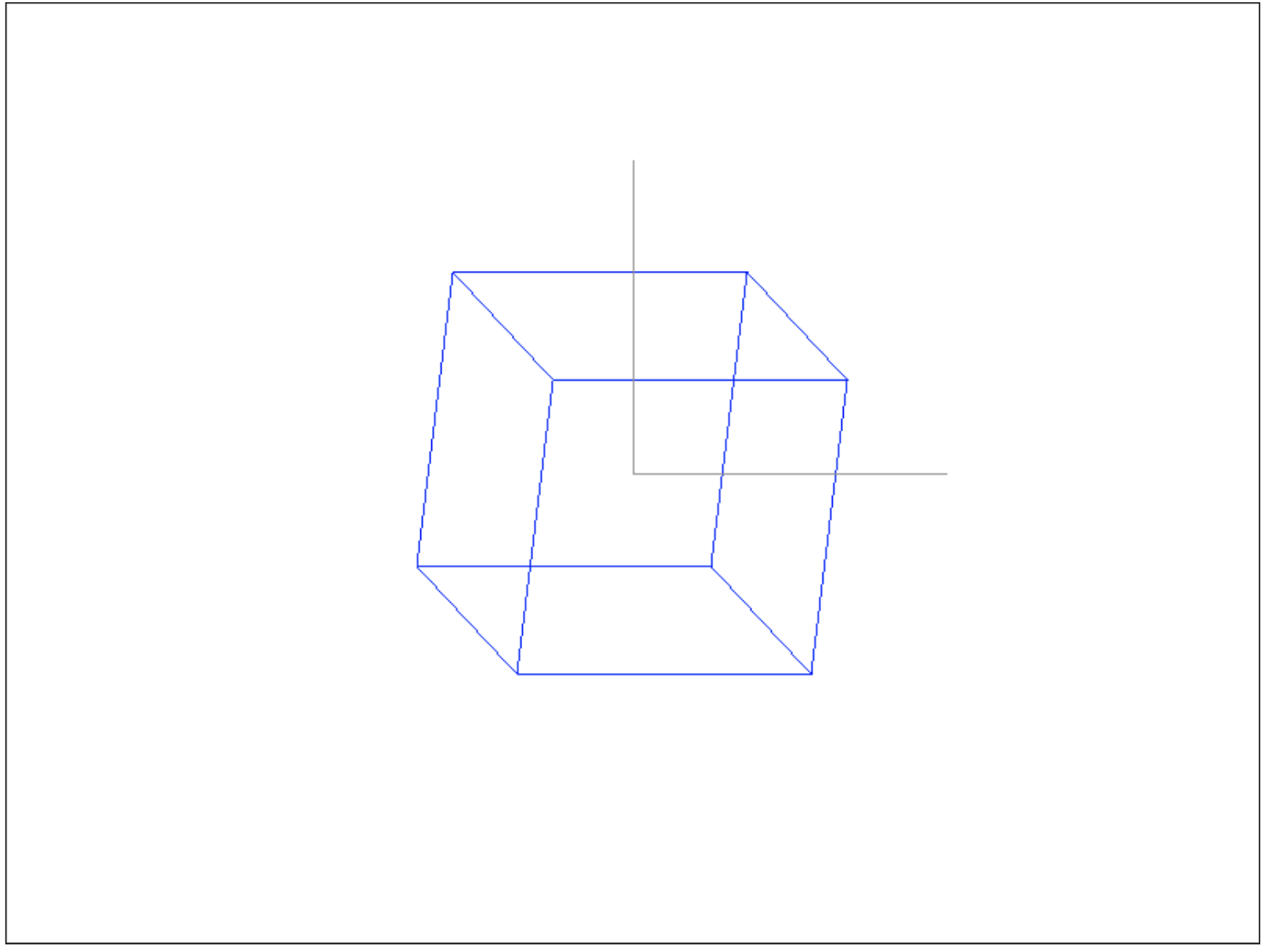
const zVector = new Vector(-1, -1, 0);
const zCoords = Vector.add(
center,
zVector.normalize().multiplyByScalar(150)
);
drawer.drawLine(
center.x, center.y,
zCoords.x, zCoords.y,
150, 150, 150
);
And as a result, you get all 3 axes of the desired length:In this example, the Z axis only shows which coordinate system we have, we drew it diagonally so that it can be seen, because the real Z axis is perpendicular to our gaze, and we could draw it with a dot on the screen, which would not be beautiful.In total, in this article we basically understood the coordinate systems, vectors and with some operations on them, matrices and their roles in coordinate transformations, sorted out the vertices and wrote a simple conveyor for visualizing the cube and axes of the coordinate system, fixing the theory with practice. All application code is available under the spoiler:Code for the entire applicationconst ctx = document.getElementById('surface').getContext('2d');
const imageData = ctx.createImageData(800, 600);
class Vector {
x = 0;
y = 0;
z = 0;
w = 1;
constructor(x, y, z, w = 1) {
this.x = x;
this.y = y;
this.z = z;
this.w = w;
}
multiplyByScalar(s) {
this.x *= s;
this.y *= s;
this.z *= s;
return this;
}
static add(v1, v2) {
    return new Vector(
        v1.x + v2.x,
        v1.y + v2.y,
        v1.z + v2.z,
    );
}
getLength() {
    return Math.sqrt(
        this.x * this.x + this.y * this.y + this.z * this.z
    );
}
normalize() {
    const length = this.getLength();

    this.x /= length;
    this.y /= length;
    this.z /= length;

    return this;
}
}
class Matrix {
static multiply(a, b) {
const m = [
[0, 0, 0, 0],
[0, 0, 0, 0],
[0, 0, 0, 0],
[0, 0, 0, 0],
];
for (let i = 0 ; i < 4 ; i++) {
for(let j = 0 ; j < 4 ; j++) {
m[i][j] = a[i][0] * b[0][j] +
a[i][1] * b[1][j] +
a[i][2] * b[2][j] +
a[i][3] * b[3][j];
}
}
return m;
}
static getRotationX(angle) {
  const rad = Math.PI / 180 * angle;

  return [
    [1, 0, 0, 0],
    [0, Math.cos(rad), -Math.sin(rad), 0],
    [0, Math.sin(rad), Math.cos(rad), 0],
    [0, 0, 0, 1],
  ];
}

static getRotationY(angle) {
  const rad = Math.PI / 180 * angle;

  return [
    [Math.cos(rad), 0, Math.sin(rad), 0],
    [0, 1, 0, 0],
    [-Math.sin(rad), 0, Math.cos(rad), 0],
    [0, 0, 0, 1],
  ];
}

static getRotationZ(angle) {
  const rad = Math.PI / 180 * angle;

  return [
    [Math.cos(rad), -Math.sin(rad), 0, 0],
    [Math.sin(rad), Math.cos(rad), 0, 0],
    [0, 0, 1, 0],
    [0, 0, 0, 1],
  ];
}
static getTranslation(dx, dy, dz) {
return [
[1, 0, 0, dx],
[0, 1, 0, dy],
[0, 0, 1, dz],
[0, 0, 0, 1],
];
}
static getScale(sx, sy, sz) {
return [
[sx, 0, 0, 0],
[0, sy, 0, 0],
[0, 0, sz, 0],
[0, 0, 0, 1],
];
}
static multiplyVector(m, v) {
return new Vector(
m[0][0] * v.x + m[0][1] * v.y + m[0][2] * v.z + m[0][3] * v.w,
m[1][0] * v.x + m[1][1] * v.y + m[1][2] * v.z + m[1][3] * v.w,
m[2][0] * v.x + m[2][1] * v.y + m[2][2] * v.z + m[2][3] * v.w,
m[3][0] * v.x + m[3][1] * v.y + m[3][2] * v.z + m[3][3] * v.w,
);
}
}
class Drawer {
surface = null;
width = 0;
height = 0;
constructor(surface, width, height) {
this.surface = surface;
this.width = width;
this.height = height;
}
drawPixel(x, y, r, g, b) {
const offset = (this.width * -y + x) * 4;
if (x >= 0 && x < this.width && -y >= 0 && -y < this.height) {
this.surface[offset] = r;
this.surface[offset + 1] = g;
this.surface[offset + 2] = b;
this.surface[offset + 3] = 255;
}
}
drawLine(x1, y1, x2, y2, r = 0, g = 0, b = 0) {
const round = Math.trunc;
x1 = round(x1);
y1 = round(y1);
x2 = round(x2);
y2 = round(y2);
const c1 = y2 - y1;
const c2 = x2 - x1;
const length = Math.max(
Math.abs(c1),
Math.abs(c2)
);
const xStep = c2 / length;
const yStep = c1 / length;
for (let i = 0 ; i <= length ; i++) {
this.drawPixel(
Math.trunc(x1 + xStep * i),
Math.trunc(y1 + yStep * i),
r, g, b,
);
}
}
clearSurface() {
const surfaceSize = this.width * this.height * 4;
for (let i = 0; i < surfaceSize; i++) {
this.surface[i] = 0;
}
}
}
const drawer = new Drawer(
imageData.data,
imageData.width,
imageData.height
);
const vertices = [
new Vector(-1, 1, 1),
new Vector(-1, 1, -1),
new Vector(1, 1, -1),
new Vector(1, 1, 1),
new Vector(-1, -1, 1),
new Vector(-1, -1, -1),
new Vector(1, -1, -1),
new Vector(1, -1, 1),
];
const edges = [
[0, 1],
[1, 2],
[2, 3],
[3, 0],
[0, 4],
[1, 5],
[2, 6],
[3, 7],
[4, 5],
[5, 6],
[6, 7],
[7, 4],
];
let angle = 0;
setInterval(() => {
let matrix = Matrix.getRotationX(20);
matrix = Matrix.multiply(
Matrix.getRotationY(angle += 1),
matrix
);
matrix = Matrix.multiply(
Matrix.getScale(100, 100, 100),
matrix,
);
matrix = Matrix.multiply(
Matrix.getTranslation(400, -300, 0),
matrix,
);
const sceneVertices = [];
for(let i = 0 ; i < vertices.length ; i++) {
let vertex = Matrix.multiplyVector(
matrix,
vertices[i]
);
sceneVertices.push(vertex);
}
drawer.clearSurface();
for (let i = 0, l = edges.length ; i < l ; i++) {
const e = edges[i];
drawer.drawLine(
sceneVertices[e[0]].x,
sceneVertices[e[0]].y,
sceneVertices[e[1]].x,
sceneVertices[e[1]].y,
0, 0, 255
);
}
const center = new Vector(400, -300, 0)
drawer.drawLine(
center.x, center.y,
center.x, center.y + 200,
150, 150, 150
);
drawer.drawLine(
center.x, center.y,
center.x + 200, center.y,
150, 150, 150
);
const zVector = new Vector(-1, -1, 0, 0);
const zCoords = Vector.add(
center,
zVector.normalize().multiplyByScalar(150)
);
drawer.drawLine(
center.x, center.y,
zCoords.x, zCoords.y,
150, 150, 150
);
ctx.putImageData(imageData, 0, 0);
}, 100);
What's next?
In the next part, we will consider how to control the camera and how to make a projection (the farther the object, the smaller it is), get to know the triangles and find out how 3D models can be built from them, analyze what normals are and why they are needed.