This article is a great entry-level training workshop on using the XBee module in conjunction with a microcontroller that has Mbed OS on board. ZigBee is a long and firmly rooted standard in Smart Home systems (for example, it is used along with Z-Wave in the Samsung SmartThings hub, see our article ), it is characterized by low power consumption, ease of use, and, most interestingly, the ability to create self-configuring mesh networks. You will see from the workshop that this is indeed so - we will look at the structure of such a network through a convenient visualizer utility.It is assumed that you already know what ZigBee is and what it is for. Now you want to connect your first XBee-module and solve your problems with it, without going into programming the module itself, but only using it as a communication interface. In the end, we will send all the data through a makeshift MQTT gateway anywhere, even to a local server, even to the Internet. We decided to show everything on the example of Mbed as the simplest and most accessible for beginners RTOS. You will be convinced that everything works “out of the box”, and you can immediately start making your project, even if before that you were dealing only with Arduino.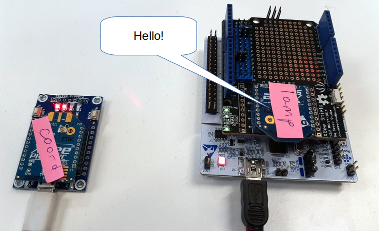 The manual will consist of the following parts:
- Connection and configuration of the XBee module
- Connect the modules to the network
- We configure the module without removing it from the shield
- Data retrieval
- Sending data
- Making a simple MQTT gateway
But first, a list of components: what is desirable to have in order to do all of the above.Required Components
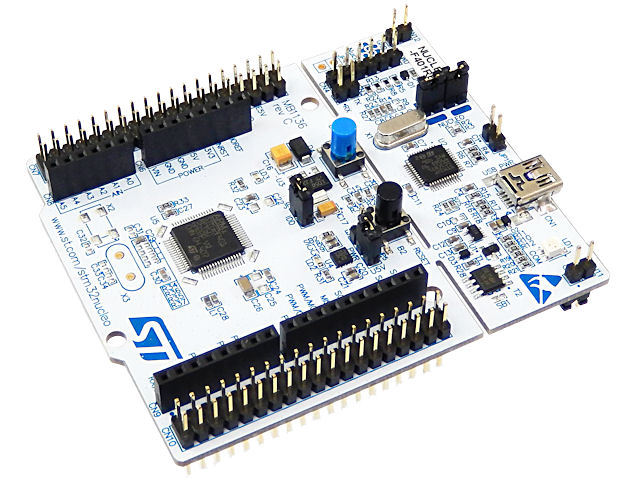
- Two Mbed-compatible boards. We recommend the STM32 Nucleo training board as relatively inexpensive and popular for educational purposes. The programming process there is maximally simplified: collect the program in an online free IDE, download the assembled firmware and “drop” it onto the board, which will appear in the system as a flash drive. What specific model to take is not important, but take not the oldest one, pay attention to the amount of memory. For example, F401RE - we give just for definiteness, so that you do not get confused in their diversity and at first incomprehensible alphabetic codes of STM processors.
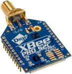
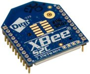
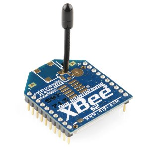
- XBee-. Digi. «» , , , MBee, , , , . / : , . / Pro: , , Pro .
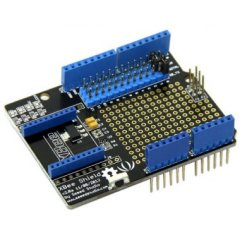
- XBee Shield V2 ( SeeedStudio). - , RX TX XBee-.
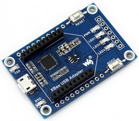
- One USB-UART converter with connector for XBee. It is needed for initial configuration. XBee modules themselves are not equipped with a USB interface (they have nothing to do with it). USB is needed solely and exclusively for communication between the module and the computer, and in the device it can work on a much simpler UART.
The slot pitch of the XBee modules is 2.0 mm - for electronics it is non-standard, in the metric system (we are usually used to seeing step 2.54 according to American standards). Therefore, unfortunately, such modules are not inserted into the breadboard and they always need an adapter.
Any adapter is suitable here, we took this one from Waveshare:
Connection and configuration of the XBee module
The simplest thing you can do with the module is to connect it to the computer directly via USB. We will immediately get access to its configuration parameters.Install XCTU
To work with XBee, there is an official XCTU program. Download it and install. The documentation says that in Ubuntu you need to add a user to a group dialoutfor working with ports not from a superuser - do this if you have not done it yet:sudo usermod -a -G dialout <username>
Download the zip archive from the link, it will contain a file .run. It needs to be made executable (via chmod +x _in the console or: right mouse button - Properties - Permissions) and run ./40002881_V.run.It is important to start the installation not from the root (without sudo), otherwise there will be problems later.The setup looks something like this: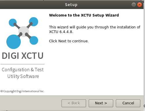
XCTU program
After installation, you can start the program by running the file appin the directory where you installed the program (by default - ~/Digi/XCTU-NG). The appearance will be as follows: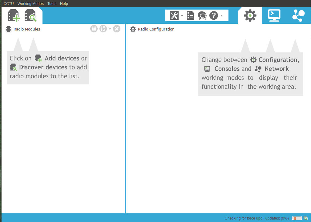 In this program, you can add your existing module connected to the USB port via an adapter. Click on the Discover button with a magnifying glass. A window pops up asking you to select a port - as you can see, the program correctly detected the port in the system
 /dev/ttyUSB0, this is our USB-UART adapter.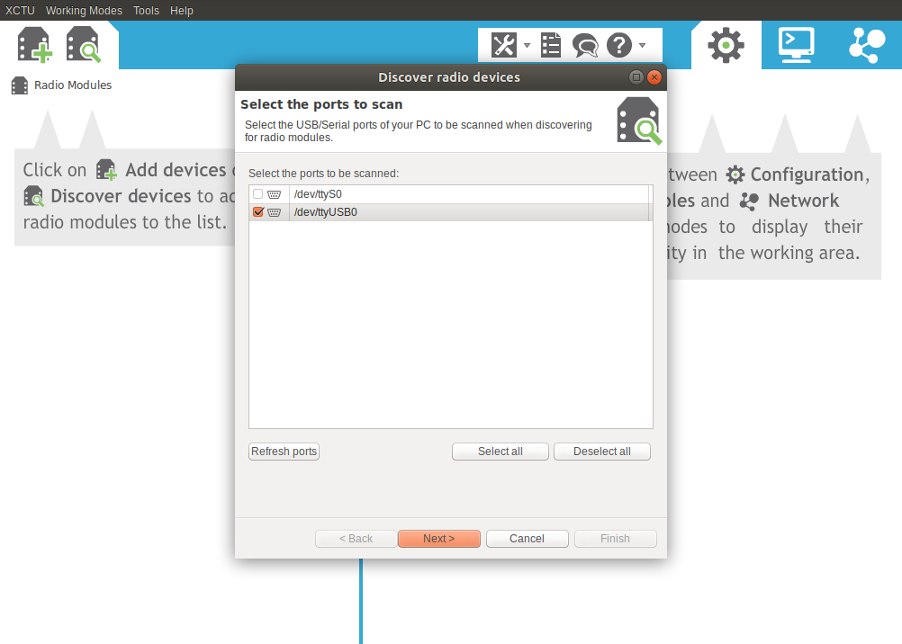 The window suggests ticking off the search. Of course, there is a temptation to check all at once to surely find your module. But then the search will go on for a very long time. In practice, it makes sense to leave the boxes checked by default, and choose the most common options for the data transfer speed, as in the picture below. Usually, new modules default to 9600, and for training purposes this is more than enough, the speed here is not critical to us.
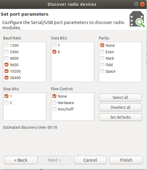 As a result, if everything is successful, you will be asked to select the module found:
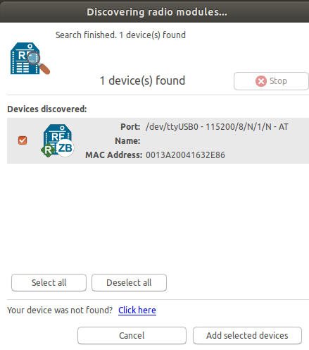 A small bug was noticed: sometimes the module was not at a non-standard speed, manual reset of the module with the Reset button during the search and resetting its baud rate to standard (9600) helped.
Change module parameters
Further we are engaged in module configuration. A bunch of parameters will drop out, most of which are initially incomprehensible. Fortunately, only a few of them will need to be changed for a quick start.Network ID - PAN ID. A common network key, it must be the same for all devices so that they are independently connected to the network. Put any number, in our case we did 42.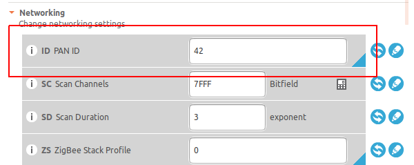 CE - Coordinator Enabled. If there is 1, then this module acts as a coordinator. If it is 0, then the module acts as a router (Router) - in fact, it simply ensures that packets pass through the network through itself. Most hosts are usually routers. We need one coordinator and two routers in our network, so put one here.There is also the role “End device” - this is a module that does not perform work on the transfer of packets, but only communicates with other routers and performs its useful functionality. Usually, he is just in sleep mode and wakes up at set intervals and finds out if there are any messages. Such a module can be powered by a battery, while the router and coordinator should always be “online” and as a result, need constant power to maintain the entire network. We will not consider such an example now, since it is more interesting for everyone to assign the role of routers and to observe how the network will automatically change its configuration.
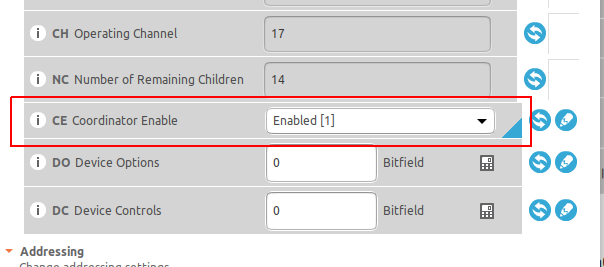 AP - API Enable.Mode of operation. XBee modules can operate in two modes: AT or API. AT-mode is easier for beginners, it is a transparent replacement of the serial port and work with the module through AT-commands. However, the API mode is much richer in functionality, it allows you to remotely configure modules, contains the sender address, returns the package delivery status, and much more. In addition, libraries for interacting with XBee assume that the device is used in the API mode. Therefore, immediately replace it with the API mode, this is done by setting the unit in the corresponding field.
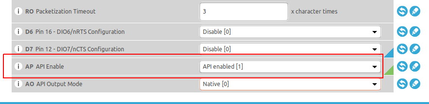 The name of the module is Node Identifier. A handy option to give your module a human-readable name. Let's give it such a name - Coordinator.
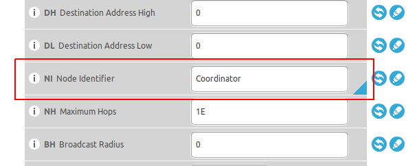 After that, you can flash the settings into the module by pressing the button with a pencil:
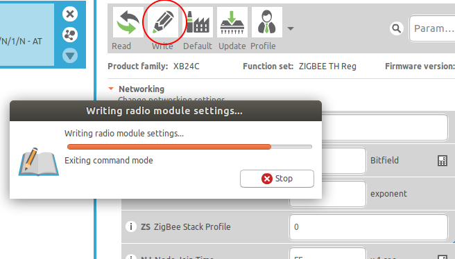
2. Connect the modules to the network
Now we will see what kind of network we get if we configure three modules. The XCTU program has a fairly convenient network visualizer, we will clearly see the topology.We will configure all three modules in turn with the following parameters:- PAN ID - total number, for example 42
- AP (API Enable) - set to 1 (work in API mode)
- NI (Node Identifier) - give the modules understandable names (Coordinator, Lamp and Switch, if we are doing, for example, a model of the Smart Home system).
- CE (Coordinator Enable) - set one of the modules to 1, it will be the coordinator.
Then apply power to all modules. Position them like this: the coordinator will be in the USB-UART converter, and the other two (routers) will be located on the XBee Shield boards on top of Nucleo.If you did everything carefully, then the beautiful will happen. The modules will automatically connect to the network. You can communicate with routers remotely through the coordinator.It looks like this. Click the "Discover radio nodes in the same network" button.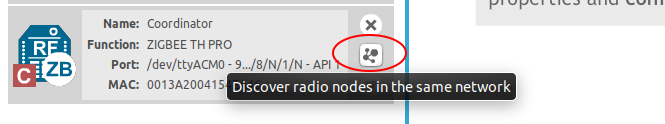 You will see that two modules were automatically detected and added:
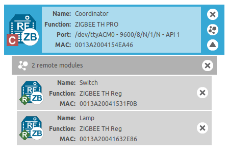 And you can change their parameters on the fly! What’s still great: now you can see the network map if you switch to the Network working mode at the top right.
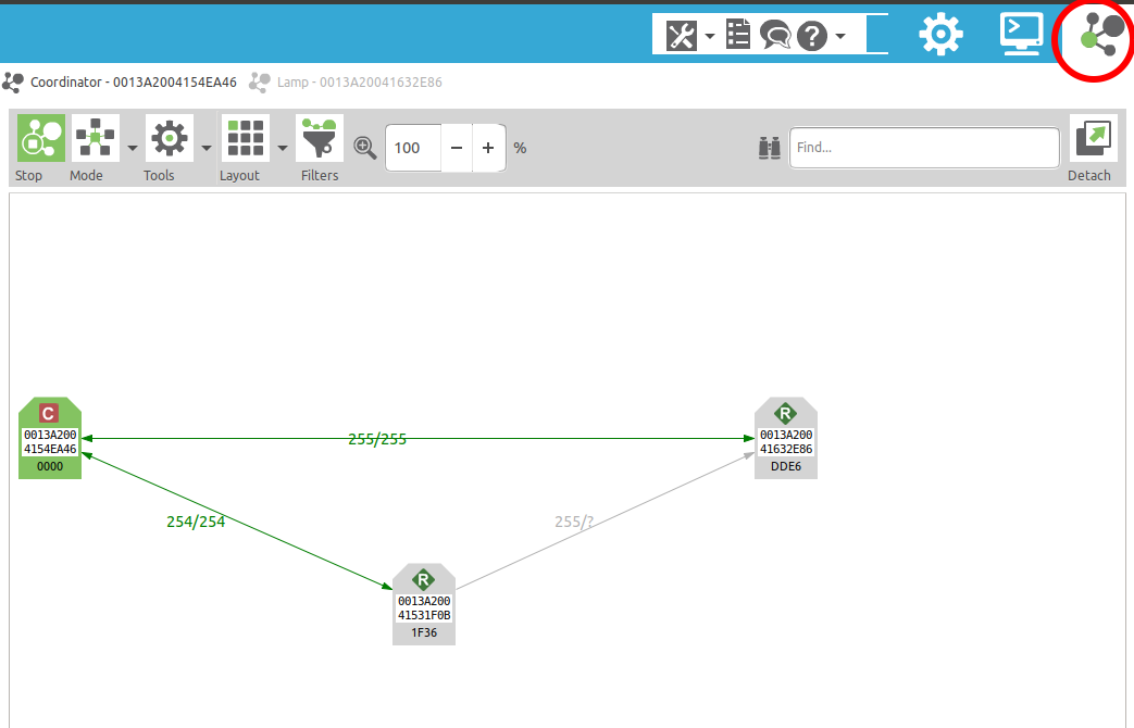 Having spread the network nodes with the mouse, you will see a triangle. Please note that traffic to the rightmost module can go in two ways. And if you move the modules in space, you will see that the picture has changed, and now, perhaps, another module will become “extreme”. This is the essence of a self-configuring network.
3. Set up the XBee module without removing it from the shield
Of course, it will be more interesting to work with the XBee-module not through a computer, but by controlling it using a program on the microcontroller. That is, connecting it to the STM32Nucleo board.Let's discuss how the XBee module can communicate with the microcontroller. And let's start with a small task: how to configure a module without removing it from the expansion shield? You must admit that moving the module back and forth is inconvenient, at the same time you want to experiment with the parameters and it’s strange why you need a separate USB-UART module, because in theory there is one in the STM32Nucleo board.The solution is simple: we need to turn the Nucleo board into a bridge between the XBee module and the USB converter on the board.General description of the idea
The STM32 microcontroller we use has several UART interfaces on board. Each such interface represents a communication channel. One of them is connected to the USB-UART converter so that we can communicate with the computer via USB in the terminal. Two others are not used yet. We will connect the XBee module to one of them, which also has such a communication channel. You can choose any UART, we have chosen for definiteness UART1.The pinout can be viewed in MBed in the upper right, by pressing the board selection button, and then on the Pinout tab. Out of habit, it can be quite difficult to perceive this colorful picture. There are a lot of things here, since the board has many interfaces, and there are two pin numbers: relative to the microcontroller (PA_5, PA_6 - pin numbering), and relative to the board (D13, D12 - inscriptions on the Nucleo board, the same numbers near the terminals).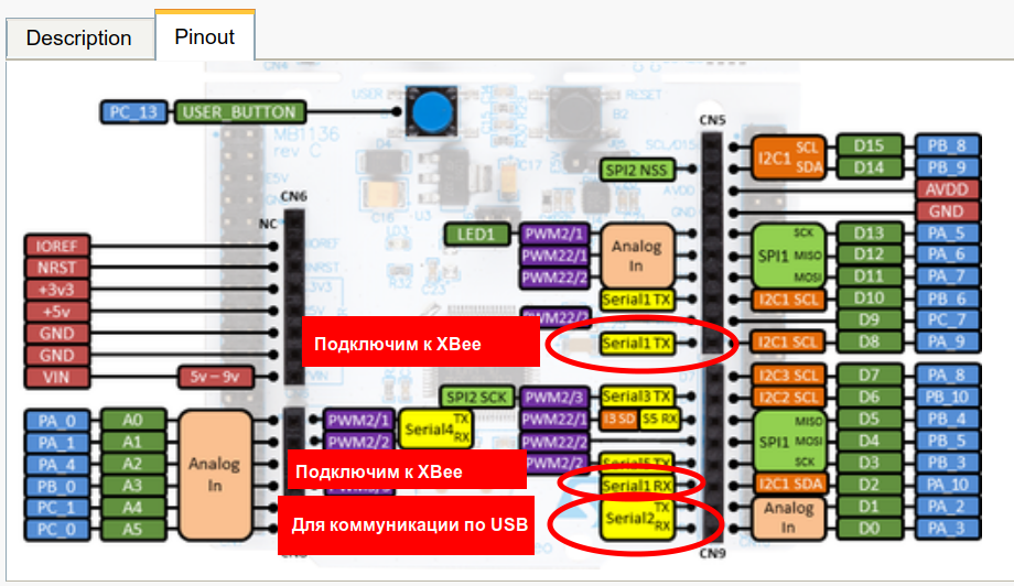 It turns out that on the microcontroller, the UART1 interface will communicate with the XBee-module, and UART2 - as before, with the computer. The internal code will redirect UART1 to UART2 and vice versa.
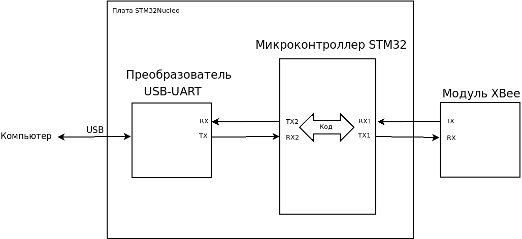 By connections, it will look like this:
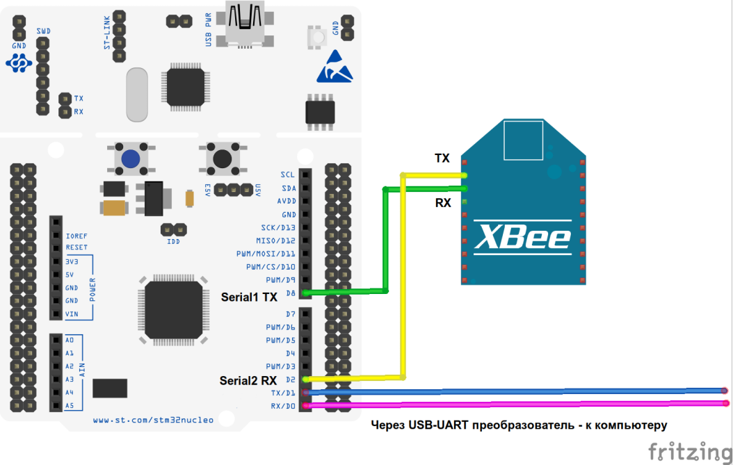
Making a “bridge” from a microcontroller
In our case, we can jumpers on the shield set the numbers to which we want to connect the ZigBee-module. TX communication module will be connected to pin 2 of the board (PA_9 on the microcontroller), and RX to pin 8 (aka PA_10).It will look like this: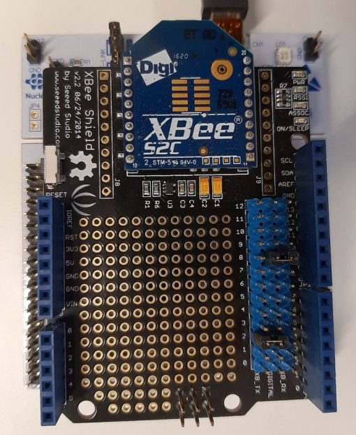 The code we took is called the Serial Bridge. This is the “bridge” between the two communication channels. We load the code into the microcontroller, which forwards everything that comes to the input from the computer via UART2, to UART1, and vice versa. As if we inserted a pipe between two sources of information (Linuxsoids will understand). We connected an XBee module to UART1.The code is very simple, the only thing you need to change in it is the pin numbers to which the device is connected. That is, make them PA_9 and PA_10, as indicated above.
#include "mbed.h"
Serial pc(USBTX, USBRX);
Serial device(PA_9, PA_10);
int main() {
pc.printf("Hello!");
while(1) {
if(pc.readable()) {
device.putc(pc.getc());
}
if(device.readable()) {
pc.putc(device.getc());
}
}
}
It is important that if you confuse the order of the conclusions - for example, you make a mistake and write PA_10, PA_9 instead of PA_9, PA_10 - the wrong order, the compiler will not report an error to you, and the program will display an error in the console upon reboot:pinmap not found for peripheral
and will not move on, that is, in principle, nothing will work.After you download this code and correctly set the jumpers on the shield, you can safely connect to the XBee module from the computer, just as you did previously with the USB-UART adapter without removing it from the shield. It will be regularly detected by the XCTU program.Even if you do not need this functionality, still check that the program is working, because in the next example we will communicate with the XBee module from the microcontroller, and the connection via UART1 should already be established (that is, jumpers are correctly set and pin numbers are indicated in the program) .4. Data acquisition
Let's look at two simple examples: how to receive and send data at the microcontroller level, using the XBee module as an external communication interface.There is an official library from manufacturers - Digi companies. It lies in the Mbed repository, there are useful comments on the use and logic of the code.First, we will learn how to get data - there is an easier example. We will have an XBee module connected to the USB-UART converter, send a greeting to the Nucleo board, and it will print this greeting to the console.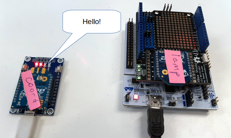 Open the project in this library. As always, import it into the online compiler as a program.
Fix libraries for S2C modules
Keep in mind that if you have S2C series modules: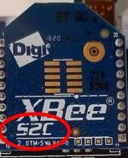 then instead of the standard library you need to use the fix: XBeeLib_Fixed . Otherwise, these programs will not work. It is added to the project simply by removing the XBeeLib library from there, and importing it into the XBeeLibFix project. Nothing more needs to be changed.So: import this library into the online compiler: The
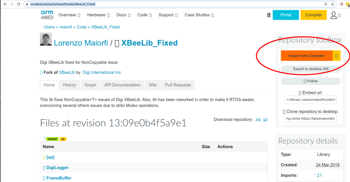 project import window will appear. There you need to choose the target - where we import:
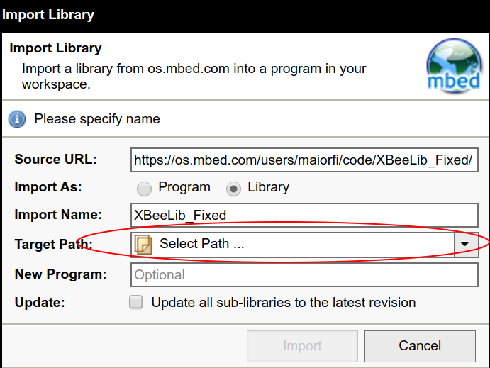 As the target project, select our example XBeeZB_Receive_Data.
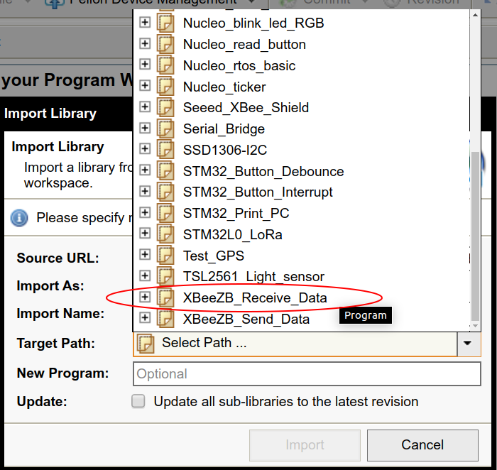 After which the library will be imported into the project, and then with a bold move we delete the wrong version of XBeeLib.
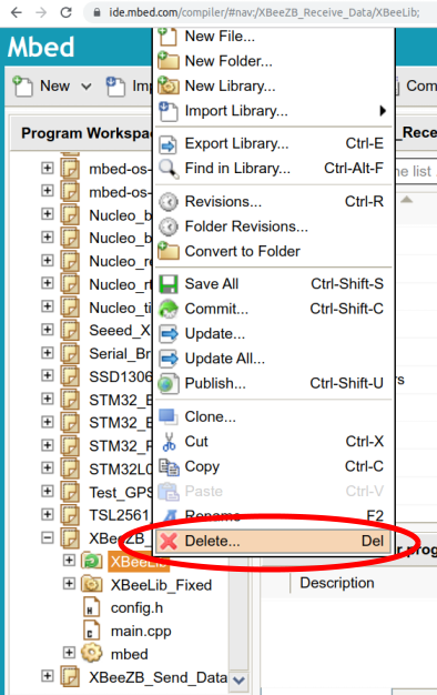
Example Compilation
So, you imported the example and replaced the library in it if necessary.Look at the sample code, it is quite simple. It defines a callback function that is called when a packet is received. This function prints the contents of the received packet to the console. So if we send her a greeting, she will print it too.In order for the example to compile, you need to write in the example the conclusions that we are responsible for communicating with the XBee-module, because the program does not know which conclusions we connected the hardware to.Therefore, we go to the config.h file and the lines in it:
Uncomment, and instead of NC we write, in accordance with what conclusions we connected the jumpers:#define RADIO_TX PA_9
#define RADIO_RX PA_10
Similarly, we modify the lines:
We write:#define DEBUG_TX USBTX
#define DEBUG_RX USBRX
If you encounter an error during compilation that you cannot find device.h, just update the Mbed library in the project tree (right-click on it -> Update).After that, the program will compile successfully, and you can download it to the board.Running example
Having looked at the console what the Nucleo board writes, you will see the following: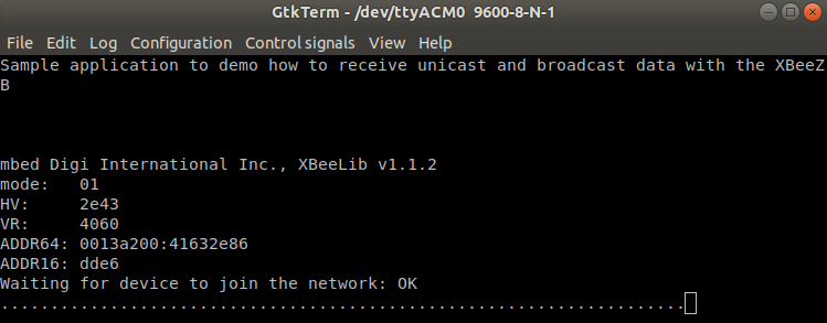 How do we send data? The easiest option: through the console in the XCTU program. Select in the main menu of the program: Tools - Send packets.
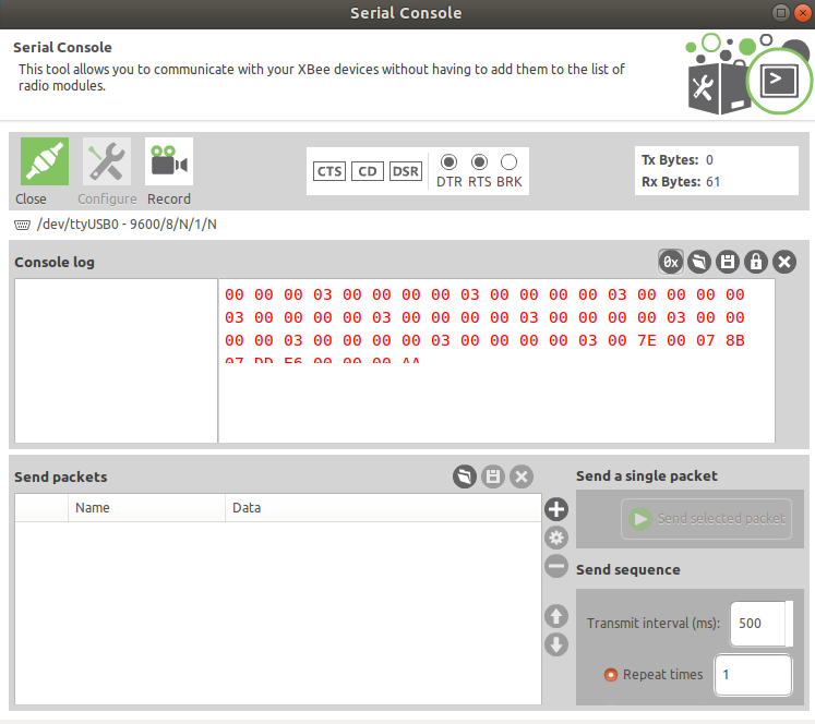 At the bottom there is a window with the words Send packets. Create a new package by clicking on the “plus” on the right. A window for creating a new package will appear. Select the HEX tab there.
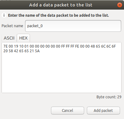 Enter there such a data sending:
7E 00 19 10 01 00 00 00 00 00 00 FF FF FF FE 00 00 48 65 6C 6C 6F 20 58 42 65 65 21 5A(using the "Send selected packet" button to the right of the packet list)You will see the result in the console of the listening module: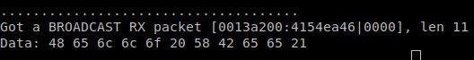 Please note that it only printed the last part of the byte set that you sent. This is the actual payload of the message. Also note that if you send “just bytes” (any random combination of bytes), the receiver will not output them.If you put a set of bytes:
 48 65 6C 6C 6F 20 58 42 65 65 21in any HEX-ASCIII converter (for example, one ), then make sure that it means "Hello XBee!"A very simple task for independent execution: modify the example code so that it displays the message text in ASCII, not HEX, and you could read this text in the terminal.5. Sending data
By analogy with the previous example, we now consider sending data.Everything is here, as in the previous example. Only with the difference that we are now opening the XBeeZB_Send_Data example .Example Compilation
It is important that if you have a S2C module (it is clearly written on it),then you will again connect the library with a fix, otherwise nothing will work for you. How to do this is described in the previous example. Also, here for successful compilation you need to specify the used controller pins, you can simply copy them from the previous example.We look at the example code itself. It mainuses several methods to send data. Choose the simplest one: send data to the coordinator. We don’t even need to register the address of the coordinator, because he is already registered on the network. Therefore, without changing the sample, we comment while all the lines at the end:send_data_to_coordinator(xbee);
And when you start, you’ll see this: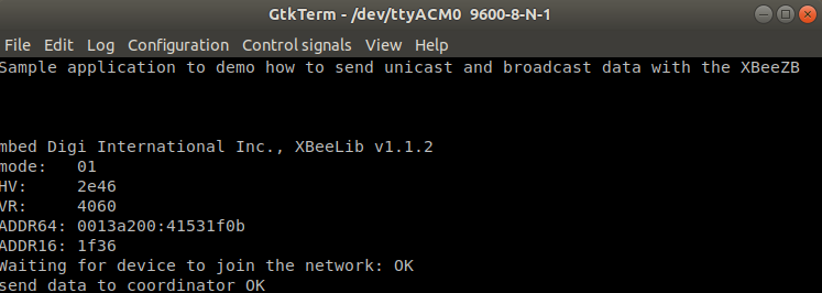 (if you don’t see it, just restart the board)How can I make sure that the data reaches the coordinator? For example, XCTU has network console mode. Turned on by the button in the upper right. In this mode, you will see all the packets on the network. Of course, at the same time, you should have a serial connection with the coordinator. And don't forget to click the Open button at the top left to make it green.
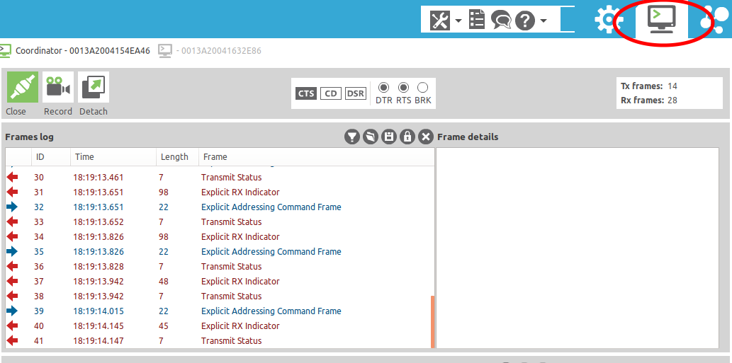 You can see detailed information about each package on the network by selecting it in the list on the left:
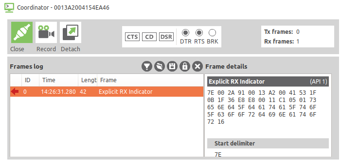 Scrolling to the end of the package contents, you will see a line with the text "send_data_to_coordinator":
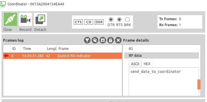 You can try other methods of sending data, but there (for example, to send to a separate selected node) you need to register the node address. You can see the addresses of all modules in the XCTU program. How to register specific addresses is exhaustively described in the example.
6. We make the MQTT gateway
Everything is great, but now I would like to somehow work with this data outside the XBee network, for example, on the Internet. One way to do this is to put the translator from XBee into the popular MQTT protocol. Then, in the usual way, we can subscribe to event notifications and send commands from the user interface, and this program can be located anywhere (if you use an external rather than a local MQTT server), and not just on our computer.Below is an instruction. In short, the program launched on the computer will exchange data from the network coordinator via a USB connection. She will transmit these data to the MQTT protocol.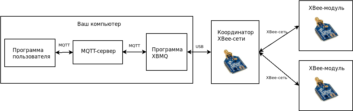
Install and configure XBMQ
The program that we will use as the MQTT gateway is called XBMQ, it is open and free. Exists in two versions:The Java version will be considered, although this is not too fundamental: we will not program it anyway, we will only install it and use it.For the program to work, you will need the RXTX library, it can be installed simply from the repository:sudo apt-get install librxtx-java
And of course, you need the JDK (Java Development Kit). It exists in two versions - from Oracle and OpenJDK, the second is recommended. Most likely, OpenJDK is already installed on your system; if not, reinstall it. Java needs a maximum of 8th, since javax.xml.bind is excluded from Java 11 and you need to choose an alternative with JDK-8 as the default option, or create a configuration for this case.Download the repository of the XBMQ program:git clone https://github.com/angryelectron/xbmq-java
After downloading the source codes, we will collect the binary file of the program. Teamant dist
will assemble a project for all major operating systems. The final compiled program will be in the folder dist.Now configure this program. Open filedist/xbmq.properties
and see there:
Uncomment and change to your parameters. The parameters are as follows: ZigBee coordinator connection port, speed, root topic (all data will fall into it), MQTT server address, username and password (if the server requires them).In this example, only the server address has changed - to the local mqtt server (standard mosquitto from Linux). Everything else was left by default:
port = /dev/ttyUSB0
baud = 9600
rootTopic = ab123
broker = tcp://127.0.0.1:1883
username = user
password = password
Before the next step, you have to install and run the local mosquitto MQTT server: sudo apt-get install mosquitto
XBMQ launch
Finally, the program can be launched. Having connected the USB-UART converter with the coordinator module inserted, run the program:./dist/xbmq.sh
When you run the script, we see the line in the console:INFO - Starting XBMQ gateway ab123/0013A2004154EA46
Last - this is exactly the address of our coordinator. If you subscribe to all topics with an external MQTT client, you will immediately see 2 messages:- In the topic
ab123/0013A2004154EA46/online- will be 1, this is Last Will (a good example of how these "special" parameters are used in real life)
- The topic
ab123/0013A2004154EA46/logwill contain the same debugging phrase “Starting XBMQ gateway ...” that you already saw in the console
Now try to send a message from some other external XBee module - for example, take an example with sending data.As a result, in the MQTT.fx program, if you subscribe to all topics (#), you will see this: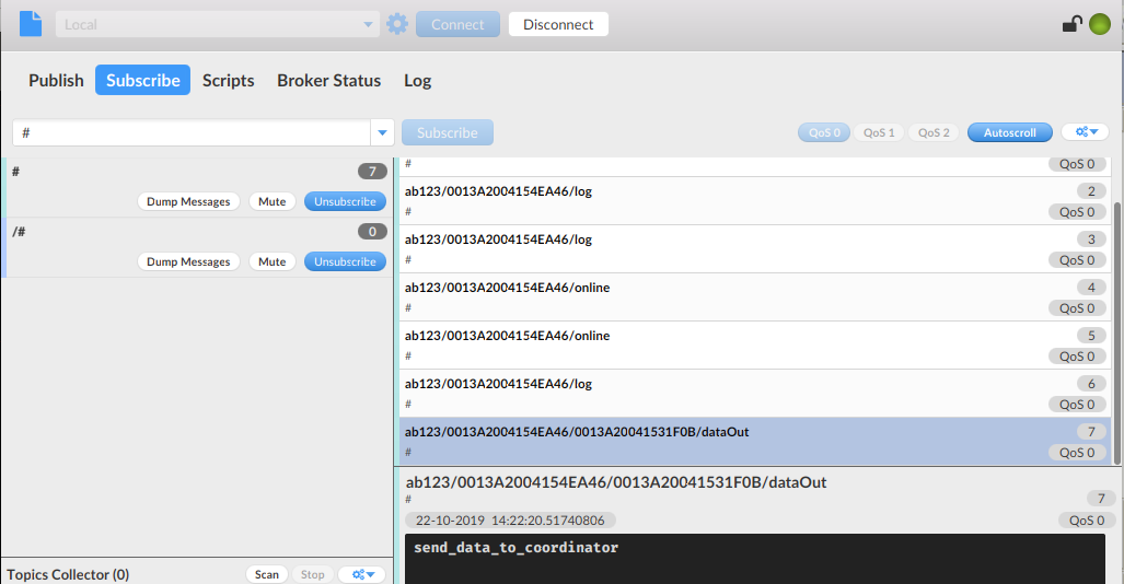 The MQTT.fx program window.That is, by starting the example studied earlier with sending a message to the coordinator, we will see this text (“send_data_to_coordinator”) as a part MQTT package. The common parent topic for us is the one specified in the program configuration ( ab123 , you can change it to your own). Next comes the address of the coordinator, then the address of the module from which the message came. Finally, this topic is called DataOut, because it is outgoing data. Of course, you will see such a picture in any other MQTT client, whether it be MQTTLens or even just
mosquitto_subin the console.A couple of final comments:- In a good way, this program should work in daemon mode. There is an xbmqd file for this, and README says how to use it.
- Keep in mind that since it
xbmqholds the port, we cannot run this program at the same time as XCTU.
Now you can work with your system using the MQTT protocol and write complex, interesting programs! Tatyana Volkova - The author of the training program on the Internet of Things track “Samsung IT Academy”, a specialist in corporate social responsibility programs at Samsung Research Center