Introduction
The market has a huge number of debug boards for every color and taste. Therefore, for novice electronics developers, the fastest way to master microcontroller programming is to buy a ready-made debug board, since significant material and time resources are required to develop and manufacture your own board.
The author of this article developed and manufactured his own board.
Your attention is invited to a draft debug board based on the STM32F107 microcontroller.
This board is the fruit of the author’s work, circuitry solutions are borrowed from the technical documentation of other similar boards. The wiring of the board may need to be adjusted, in particular, the wiring of the RT8201BL chip for Ethernet. The connection of the board to the network via Ethernet was tested using a ready-made design.
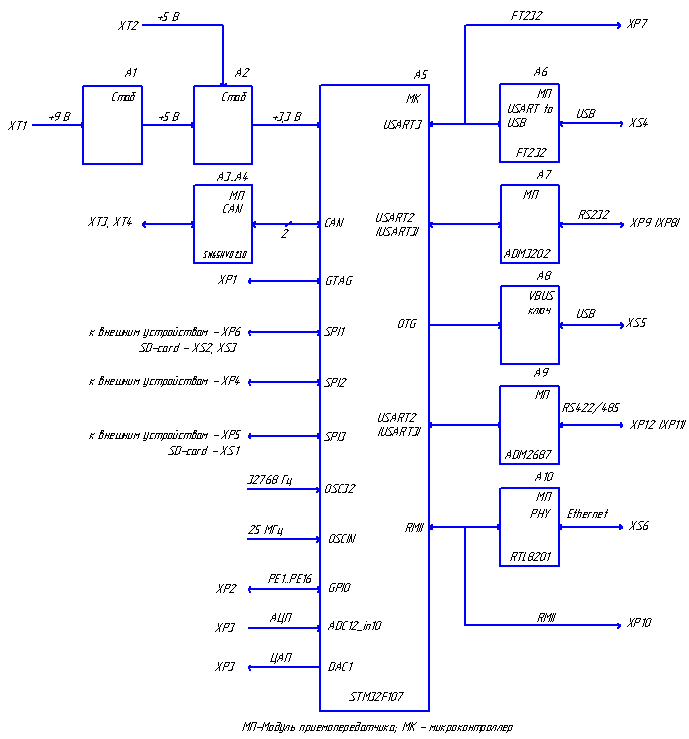
The controller module board is a universal tool based on the STM32F107VCT6 microcontroller, designed to be embedded in various systems as a control unit.
Features of the debug board:
- STM32F107VCT6 microcontroller: 72 MHz Cortex-M3, 256 Kbytes of program flash memory, 64 Kbytes of RAM, two 12-bit ADCs (16 external channels), two-channel 12-bit DAC, Ethernet MAC 10/100, USB OTG, 2xCAN, 5 USART, 3x SPI, I2C, SDIO, LQFP100 package;
- USB OTG port with mini USB connector;
- 2 CAN interfaces;
- USB bridge - USART to FT232RL;
- 2 RS-232 interfaces or 2 RS-422/485 interfaces with galvanic isolation;
- 10 / 100MBod RMII PHY with Ethernet RJ-45;
- SD / MMC and microSD memory card slots;
- 16 lines of the microcontroller's PE port are routed to the connector;
- 3 SPI connectors for connecting external devices;
- 25 MHz quartz crystal;
- clock quartz resonator 32768 Hz;
- Reset Button
- JTAG connector for connecting a JTAG programmer or debugger;
- supply voltage +9 V or +5 V;
- power supply to the controller core from a 3 V battery;
- : 160125 ; : 150115 .
1.
3D- 2.
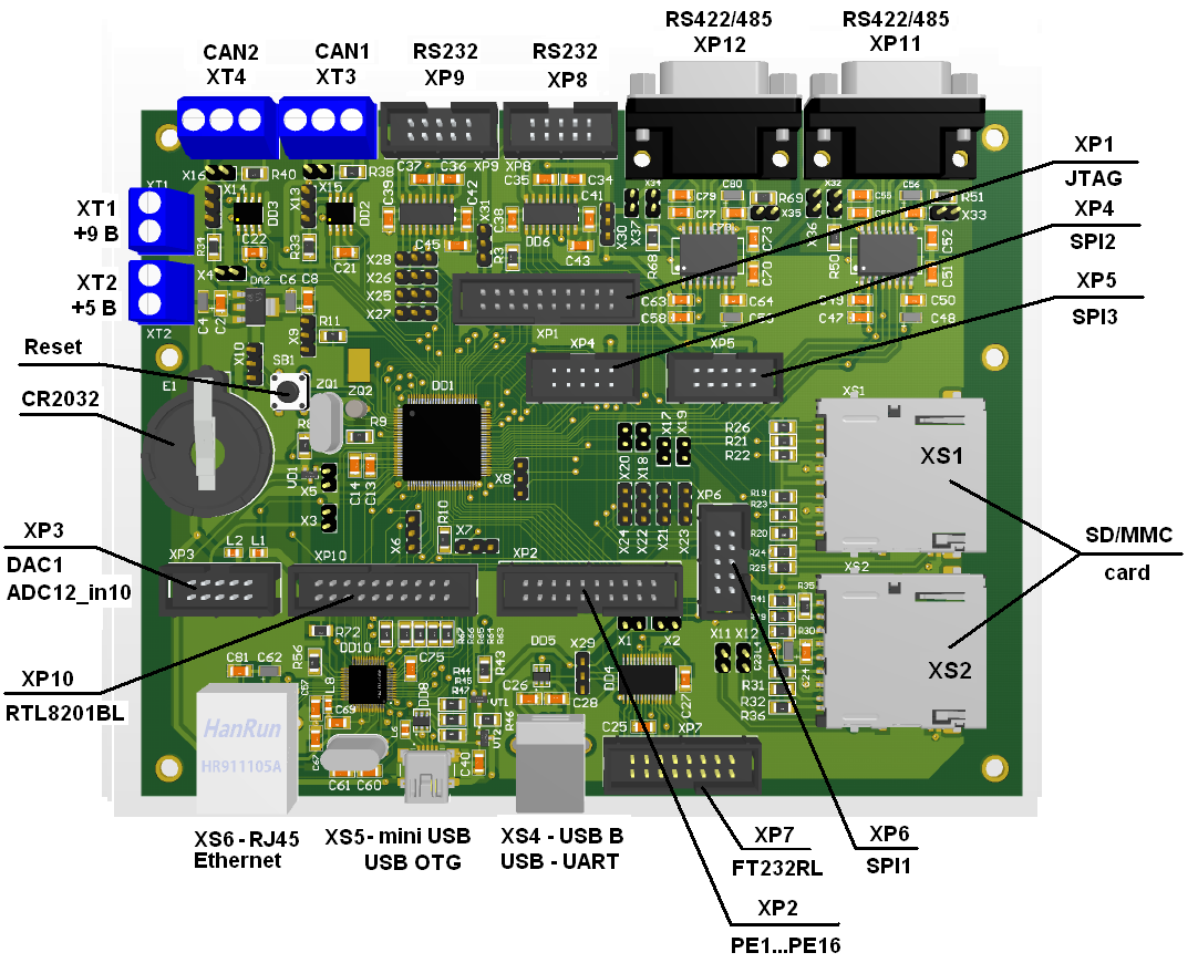
1.
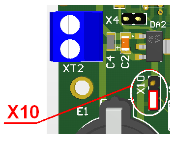
XT1 XT2. XT1 +7,5 +9 . XT2 + 5 . +9 X4. CR2032 X10.
X10
3,3 :

:
2.
Reset . X7 X9 .
-, X7, , .
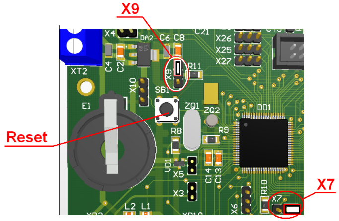
X7 , :

X9 :

,
X9 :

1.3 CAN
SN65HVD230 CAN. CAN . R S.
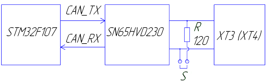
XT3 XT4. X15, X16.
X13 X14 CAN – .
, :

.
:

.
1.4 RS232
ADM3202 USART RS232.
ADM3202:
- 460 /;
- MAX3222/32 LTC1385;
- IEC1000-4-2 (801.2) RS-232:
- ±8 :
- ±15 :
XP8, XP9:
3 — RS232_RXD
4 — RS232_RTS
5 — RS232_TXD
6 — RS232_CTS
9, 10 — GND
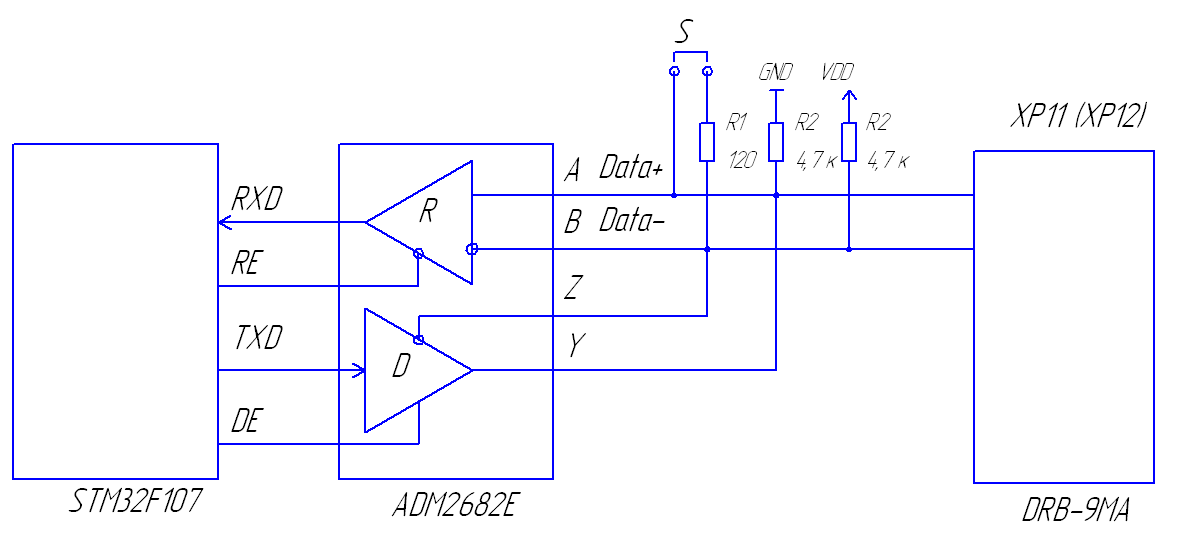
1.5 RS422/485
ADM2682E USART RS422/485.
ADM2682E/ADM2687E Analog Devices 5 , ±15 ESD .
ADM2682E/ADM2687E DC-DC . iCoupler Analog Devices, Inc., 3- , , Analog Devices isoPower. 5 3.3 , , RS-422/485 .
- RS-485/RS-422 5 , ;
- isoPower ;
- ±15 ESD RS-485 /;
- ANSI/TIA/EIA-485-A-98 ISO 8482:1987(E);
- 5 3.3 ;
- 256 ;
- ;
- : >25 /;
- : 500 / ADM2682E 16 M/ ADM2687E.
P8 (XP9)
1 RS422/485_TX1+
2 RS422/485_TX1-
3 RS422/485_GND
4 RS422/485_RX1-
5 RS422/485_RX1+
6 RS422/485_GND
7 RS422/485GND
8 RS422/485+5V
9 RS422/485_GND
4- RS422 – .

. RX+ RX- XP11 XP12 X34 X32 .

2- RS485 RX- TX- RX+ TX+ , . 1,5 2, 4.
1.6 USB — USART FT232RL.
FT232RL:
- USB — (UART);
- USB ;
- UART 7 8 , 1 2 , ;
- 300 3 RS422 /RS485 / TTL 300 1 RS-232;
- CBUS;
- / ;
- , , , 6, 12, 24 48 ;
- ;
- EEPROM 1024 ;
USART2 USART3 STM32F107 RS232 RS422 c . USB — USART FT232RL USART3.
1.7 Ethernet
Ethernet RTL8201BL, MII (Media Independent Interface). RTL8201BL 25,0.
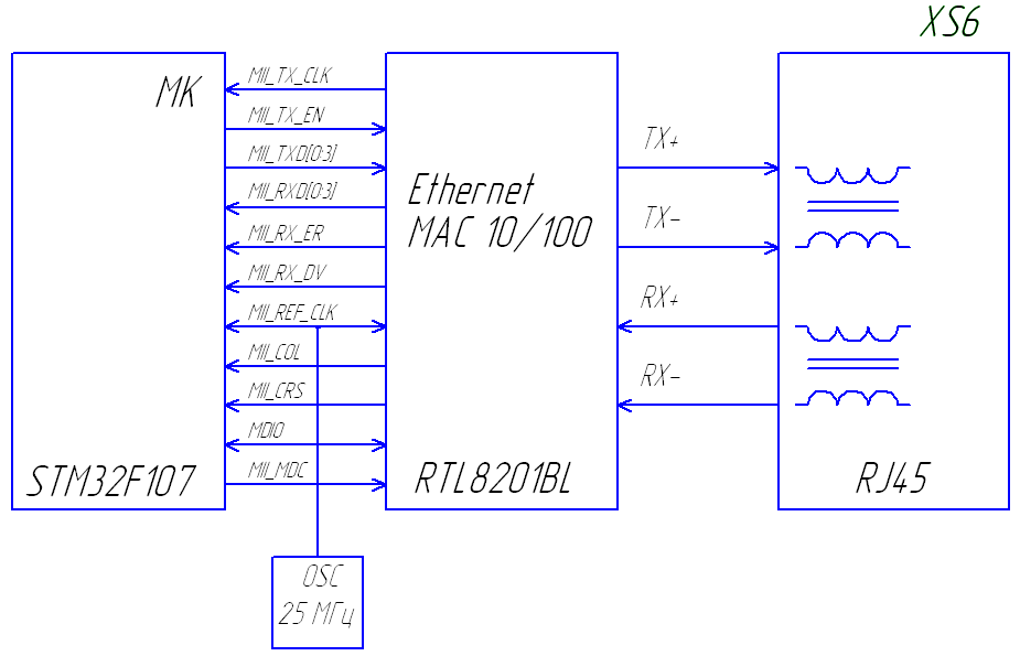
STM32F107VCT6 Ethernet USB.
1.8 USB
USB- : Host, Device OTG (On-The-Go). USB mini USB XS5.
1.9 SD MicroSD
SD, SDHC microSD, microSDHC. SPI .

SDcard_Detect 0. SDcard_Detect AXA2R73361. SDcard_WP , .
SDcard_Detect SDcard_WP +3,3 , , .
SD, SDHC XS1 (AXA2R73361), SPI3, XS2 (AXA2R73361), SPI1.
1.10 SPI
SD – SPI XP4…XP6. BH-10. SPI : , , . . XP2 PE.
The JTAG XP1 connector is used for programming and debugging:
1 + 3.3V
2 + 3.3V
3 TRST
4 GND
5 TDI
6 GND
7 TMS / SWDIO
8 GND
9 TCK / SWCLK
10 GND
11
12 GND
13 TDO / SWO
14 GND
15 RESET
16 GND
17 NC
18 GND
19 NC
20 GND
Link to circuit and board file