Hello! I want to introduce you to the Rust Embedded project . It allows us to use the Rust programming language for development for embedded platforms (Embedded Linux / RTOS / Bare Metal).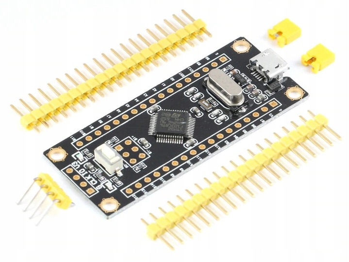 In this article, we will consider the components that are necessary to begin development for Cortex-M3 microprocessors. After that, we will write a simple example - blinking of the built-in LED.To do this, we need an affordable and cheap Chinese debug board STM32F103C8T6 or Black Pill (due to the black color and small size). There is also a version of the board in blue - Blue Pill. I do not recommend it, since I heard that it has the wrong resistor, which causes problems when using the USB port. Its second difference from Black Pill in the arrangement of pins (conclusions). But more on that later.We will also need a programmer for STM32 debug boards. In this article, we will use the cheap and affordable Chinese ST-Link V2 programmer.
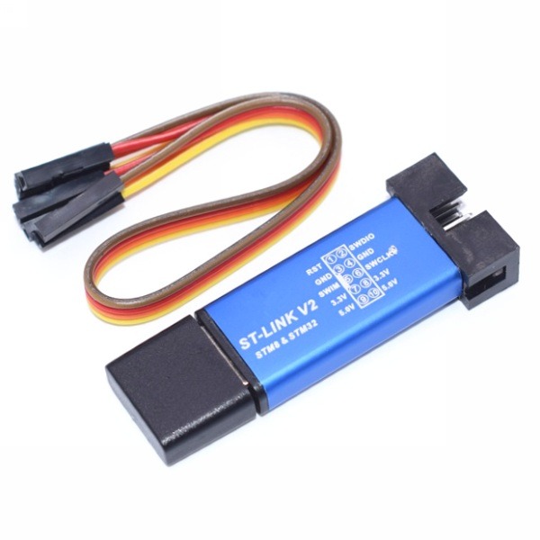
Rust Compiler Version
To get started, you need to make sure your compiler version is 1.31 or more recent. You can check your compiler version by entering the command:> rustc --version
Component Installation
Now we can begin to install the necessary components.GNU Arm Embedded Toolchain
We will need a debugger for ARM chips - arm-none-eabi-gdb. Launch the installer and follow the instructions. At the end of the installation, be sure to check the " Add path to environment variable " option .Download linkAfter installation, you can check if everything is in order by entering the following at the command line:> arm-none-eabi-gdb -v
If everything is in order, then you will see the version of the installed component.ST-Link Driver
Let's move on to installing the driver for the ST-Link programmer.Follow the instructions of the installer and make sure that you install the correct ( sixty-four bit or thirty-two bit ) version of the driver depending on the bit depth of your operating system.Link to downloadST-Link Tools
The next step is to install the tools necessary for the firmware - ST-Link Tools. Download the archive and unzip it to any convenient place, you also need to specify the path to the bin subfolder ( stlink-1.3.0 \ bin ) in the environment variable " PATH ".Link to downloadcargo-binutils
Finally, install the package cargo-binutils, this is done by two commands in the console.> cargo install cargo-binutils
> rustup component add llvm-tools-preview
This completes the installation of components.Creating and setting up a project
To continue, we need to create a new project with the name " stm32f103c8t6 ". Let me remind you, this is done by the command:> cargo new stm32f103c8t6
Project Dependencies and Optimization
Connect the necessary libraries in the Cargo.toml file :[package]
name = "stm32f103c8t6"
version = "0.1.0"
authors = ["Nick"]
edition = "2018"
# Cortex-M3
[dependencies]
cortex-m = "*"
cortex-m-rt = "*"
cortex-m-semihosting = "*"
panic-halt = "*"
nb = "0.1.2"
embedded-hal = "0.2.3"
# stm32f1
[dependencies.stm32f1xx-hal]
version = "0.5.2"
features = ["stm32f100", "rt"]
# `cargo fix`!
[[bin]]
name = "stm32f103c8t6"
test = false
bench = false
#
[profile.release]
codegen-units = 1 #
debug = true # , Flash
lto = true #
Also, you can see that, at the end of the file, code optimization has been enabled.The cortex-m-rt library requires us to create a file in the root directory of the project, it must be called " memory.x ". It indicates how much memory our device has and its address:MEMORY
{
FLASH : ORIGIN = 0x08000000, LENGTH = 64K
RAM : ORIGIN = 0x20000000, LENGTH = 20K
}
Setting the target platform and default compilation goals
It is necessary to set the target platform for the compiler, this is done by the command:> rustup target add thumbv7m-none-eabi
After that, create the " .cargo " folder in the root directory and the " config " file in it .The contents of the config file :[target.thumbv7m-none-eabi]
[target.'cfg(all(target_arch = "arm", target_os = "none"))']
rustflags = ["-C", "link-arg=-Tlink.x"]
[build]
target = "thumbv7m-none-eabi" # Cortex-M3
In it, we identified the default compilation goal, this allows us to compile our code into an ARM .elf file with a simple and familiar command:> cargo build --release
Example
To make sure that it works, consider the simplest example - blinking an LED.The contents of the main.rs file :#![deny(unsafe_code)]
#![no_std]
#![no_main]
use panic_halt as _;
use nb::block;
use stm32f1xx_hal::{
prelude::*,
pac,
timer::Timer,
};
use cortex_m_rt::entry;
use embedded_hal::digital::v2::OutputPin;
#[entry]
fn main() -> ! {
let cp = cortex_m::Peripherals::take().unwrap();
let dp = pac::Peripherals::take().unwrap();
let mut flash = dp.FLASH.constrain();
let mut rcc = dp.RCC.constrain();
let clocks = rcc.cfgr.freeze(&mut flash.acr);
let mut gpiob = dp.GPIOB.split(&mut rcc.apb2);
let mut led = gpiob.pb12.into_push_pull_output(&mut gpiob.crh);
let mut timer = Timer::syst(cp.SYST, &clocks)
.start_count_down(1.hz());
loop {
block!(timer.wait()).unwrap();
led.set_high().unwrap();
block!(timer.wait()).unwrap();
led.set_low().unwrap();
}
}
In the first line, using the - attribute #![deny(unsafe_code)], we remove the possibility of using unsafe code.In the second line, we placed the attribute #![no_std], it is required, because we are creating an application for bare iron, and the standard library needs an operating system.Next comes an attribute #![no_main]that tells the compiler that we are not using the default default function with the argument vector and return type. This does not make sense, since we do not have an operating system or other runtime that calls the function and processes the return value.After the attributes, we plug the necessary modules into the scope.This is followed by a function, in our case, out of habit, we called it -main(). This is the entry point to the program, it is determined by the attribute #[entry].Inside the main function, we create a handle to a peripheral object that “owns” all peripheral devices.After that, we can set the pin responsible for the LED built into the board to the output. Since in my case it is a Black Pill board , the LED in it is connected to pin B12 . If you have a Blue Pill board , then pin C13 is responsible for the built-in LED . Therefore, we set pin B12 as a push-pull output and assign it to a variable led.Now we can set the update event trigger time for the system timer, and save it in a variabletimer. In our example, this time is one second.Then, in an endless loop, we can describe the logic of our program. It is very simple, first timerblocks the execution of the program until the time specified in it has passed. The next step is to set the pin of the built-in LED to high , so it lights up. After that, the program execution is again blocked by the same timer, for one second. And the pin of the LED is set to low , therefore it goes out. Further, the program is cyclically repeated.Compilation
Now that we have figured out the program code and logic, we can compile it into a .elf file with the command:> cargo build --release
This format contains not only binary code, but also some headers and more. This is useful when the file is launched by other software, such as the operating system or bootloader.But, to run the program on bare metal, we need not a .elf file , but a .bin file . A .bin file is a software image that can be written byte into the microcontroller's memory. The .elf file can be converted to a .bin file using the command:> cargo objcopy --bin stm32f103c8t6 --target thumbv7m-none-eabi --release -- -O binary stm32f103c8t6.bin
Now our binary file is ready for firmware.Connection
We will flash the board using the ST-Link V2 programmer. To do this, you must first connect it to the board.On the programmer case there is a pin arrangement of the connector. You need to pay attention to the cutout in the connector, it is also displayed on the diagram, which allows you to understand how to make the connection.Connect the 3.3V and GND pins of the programmer with the corresponding pins on the board. Ping SWDIO connect to pin the DIO , and pin SWCLK to pin the CLK .After connecting the board to the programmer, we can connect the ST-Link to the computer.Attention!Before connecting, disconnect all other power sources from the board, if any, otherwise it may damage the board or computer.Now we can check the connection:> st-info --descr
In the console, we should see the line " F1 Medium-density device ".Firmware
Optionally, before flashing, you can clear the board’s memory if something is written on it:> st-flash erase
Finally, we can start the firmware:> st-flash write stm32f1.bin 0x8000000
If everything is done correctly, you should see a blinking LED. Congratulations!Conclusion
So, to flash the board, you must use this set of commands entered sequentially:> cargo build --release
> cargo objcopy --bin stm32f103c8t6 --target thumbv7m-none-eabi --release -- -O binary stm32f103c8t6.bin
> st-flash erase
> st-flash write stm32f1.bin 0x8000000
To simplify our life, we can create a .bat file with these commands and run it from the console.From the author
If you are interested in these guides, welcome to my YouTube channel .Also, recently, I started a Telegram channel where I publish various translations of manuals and books, news, humor and other things related to the Rust programming language. There you can find links to several chatrooms in order to ask your questions and get help, submit your projects or just chat with like-minded people.Thank you for the attention!