 It is assumed that the reader already has an initial knowledge of the C language, knows something about Zigbee, the cc2530 chip, methods for flashing it and using it, and is also familiar with projects like zigbee2mqtt. If not, get ready or go read it at https://myzigbee.ru and https://www.zigbee2mqtt.io/ Thearticle is written first in detail, but gradually accelerates and does not stop at the details, but describes the finished firmware code. If someone is not interested in reasoning, then just open the firmware sources and read them.The source code of the finished firmwareThe code and development approach does not claim to be ideal. "I'm not a magician, I'm just learning."
purpose
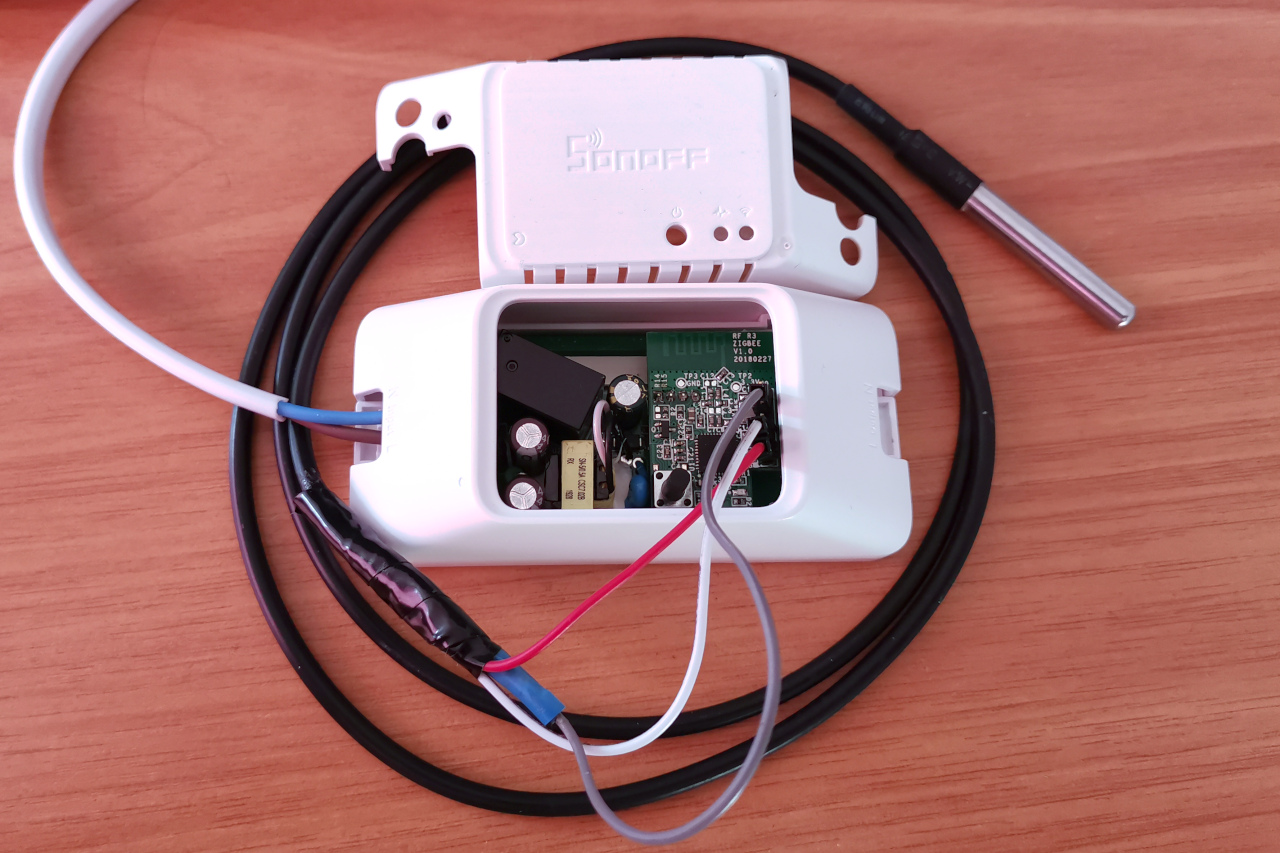
The main goal is to understand how to write firmware for Z-Stack for a long time. Therefore, I decided to implement an alternative firmware for the finished equipment ( Sonoff BASICZBR3 relay was chosen as an example ) and add the ability to connect the popular ds18b20 temperature sensor.In addition, I wanted to show beginners Zigbee developers an example of developing firmware for the TI cc2530 chip on Z-Stack.1. Preparation
To start development, you need to download and install Z-Stack 3.0.2 - this is an SDK for developing firmware with examples and documentation.You also need to download and install IAR Embeded Workbench for 8051 - this is a development environment with the ability to compile for TI cc2530 chips. The free use period is 1 month (but the seeker will find a solution).For development and debugging, I use CCDebugger - it allows not only flashing cc2531 / cc2530 chips, but also debugging the application in the IAR environment. To simplify the experiments, prototyping and debugging I do on the devboard and the corresponding cc2530 module:
2. Creating a new application
We create a new project based on GenericApp. This is an example of a basic Z-Stack application. It is located in the Z-Stack 3.0.2 \ Projects \ zstack \ HomeAutomation \ GenericApp folder.We copy it nearby and rename it, for example, to DIYRuZRT (let's call the application for our device).Inside the CC2530DB folder there are files:- GenericApp.ewd - project settings for C-SPY
- GenericApp.ewp - project file
- GenericApp.eww - Workspace
Rename the files to DIYRuZRT.eww and DIYRuZRT.ewp.Inside all the files (including the Source folder), we also change all references to GenericApp to DIYRuZRT.Now open the DIYRuZRT.ewp project in IAR. We select the configuration of RouterEB and perform Rebuild All.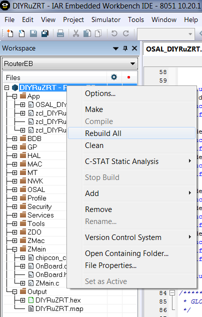 The RouterEB folder will be created in the CC2530DB folder, and the DIYRuZRT.d51 file will appear inside the EXE folder - this file is convenient for flashing and debugging from IAR.But if we need to flash the firmware via SmartRF Flash Programmer, then we will make small changes. To do this, in the project settings in the Link section on the Output tab, change the settings for the Output file and Format:
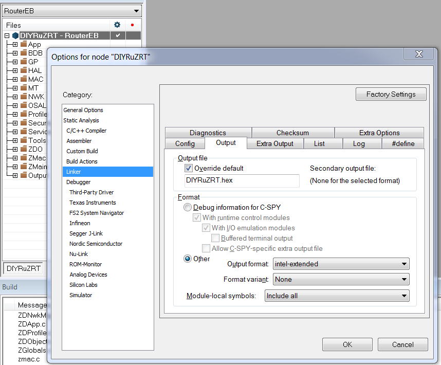 After that, the DIYRuZRT.hex firmware file will be created in the EXE folder, convenient for flashing from other tools and in other ways .But after uploading this firmware, the device does not connect to the network. Well, we will understand.
3. A bit of terminology
Zigbee terminology has the following concepts:- Endpoint - The description point of the end device. Usually in simple devices one endpoint. There can be several of them in multifunction devices, as well as in devices with different interaction profiles (one profile - one endpoint).
- Cluster (cluster) - a set of attributes and commands related to a single functional (on / off, dimming, temperature measurements, etc.). The cluster indicates the opportunities realized by the endpoint. In one endpoint, you can implement several different clusters, but not the same ones.
- Attribute (attribute) - a characteristic of a cluster whose value can be read or written. A cluster can have many attributes.
- Command - A control message that the cluster can process. A team may have parameters. This is implemented by a function that is executed when a command and parameters are received.
Types of clusters, attributes, commands are standardized in the Zigbee Cluster Library. But manufacturers can use their own clusters, with their own attributes and teams.Some pitiful producers do not care about the standards and do something about the standard. Then you have to adapt to them. Z-Stackterminology also has its own concepts , for example:- OSAL (Operating System Abstraction Layer) - the abstraction level of the Operating System. Here they operate with tasks (tasks), messages (messages), events (events), timers (timers) and other objects.
- HAL (Hardware Abstraction Layer) - level of equipment abstraction. Here they operate with buttons (keys), LEDs (leds), interrupts (Interrupt), etc.
The hardware layer provides isolation of the program code and the equipment that it controls. The operational level provides mechanisms for building and interacting between application elements.Using this all awaits you below and, in principle, when developing firmware.4. What do we have inside the base application?
The application code is located in the Source folder:- OSAL_DIYRuZRT.c —
- zcl_DIYRuZRT.h —
- zcl_DIYRuZRT.c —
- zcl_DIYRuZRT_data.c — ,
OSAL_DIYRuZRT.c - the main file in which the array of task handlers (task) pTaskEventHandlerFn tasksArr is populated and the osalInitTasks initialization function is implemented .All other files are needed to implement these initializers and handlers.The list of task handlers pTaskEventHandlerFn tasksAr r is populated with function references. Some tasks are connected / disconnected by the corresponding compilation directives.You can view and configure compilation directives in the Defined symbols compiler options: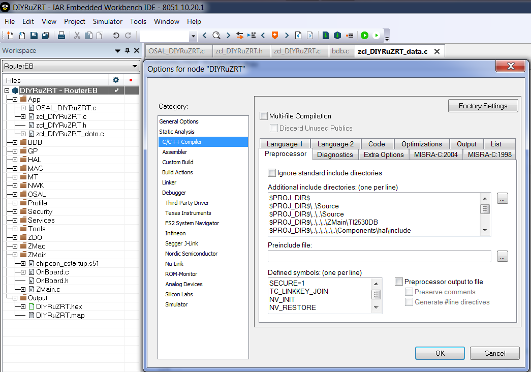
const pTaskEventHandlerFn tasksArr[] = {
macEventLoop,
nwk_event_loop,
#if !defined (DISABLE_GREENPOWER_BASIC_PROXY) && (ZG_BUILD_RTR_TYPE)
gp_event_loop,
#endif
Hal_ProcessEvent,
#if defined( MT_TASK )
MT_ProcessEvent,
#endif
APS_event_loop,
#if defined ( ZIGBEE_FRAGMENTATION )
APSF_ProcessEvent,
#endif
ZDApp_event_loop,
#if defined ( ZIGBEE_FREQ_AGILITY ) || defined ( ZIGBEE_PANID_CONFLICT )
ZDNwkMgr_event_loop,
#endif
#if defined ( INTER_PAN )
StubAPS_ProcessEvent,
#endif
#if defined ( BDB_TL_INITIATOR )
touchLinkInitiator_event_loop,
#endif
#if defined ( BDB_TL_TARGET )
touchLinkTarget_event_loop,
#endif
zcl_event_loop,
bdb_event_loop,
zclDIYRuZRT_event_loop
};
osalInitTasks is the application start-up function that registers tasks performed by the application.Registration of tasks is performed in order, and each task gets its own number. It is important to follow the same order as in the tasksArr array , as handlers are called according to the task number.void osalInitTasks( void )
{
uint8 taskID = 0;
tasksEvents = (uint16 *)osal_mem_alloc( sizeof( uint16 ) * tasksCnt);
osal_memset( tasksEvents, 0, (sizeof( uint16 ) * tasksCnt));
macTaskInit( taskID++ );
nwk_init( taskID++ );
#if !defined (DISABLE_GREENPOWER_BASIC_PROXY) && (ZG_BUILD_RTR_TYPE)
gp_Init( taskID++ );
#endif
Hal_Init( taskID++ );
#if defined( MT_TASK )
MT_TaskInit( taskID++ );
#endif
APS_Init( taskID++ );
#if defined ( ZIGBEE_FRAGMENTATION )
APSF_Init( taskID++ );
#endif
ZDApp_Init( taskID++ );
#if defined ( ZIGBEE_FREQ_AGILITY ) || defined ( ZIGBEE_PANID_CONFLICT )
ZDNwkMgr_Init( taskID++ );
#endif
#if defined ( INTER_PAN )
StubAPS_Init( taskID++ );
#endif
#if defined( BDB_TL_INITIATOR )
touchLinkInitiator_Init( taskID++ );
#endif
#if defined ( BDB_TL_TARGET )
touchLinkTarget_Init( taskID++ );
#endif
zcl_Init( taskID++ );
bdb_Init( taskID++ );
zclDIYRuZRT_Init( taskID );
}
Our application registered the function handler zclDIYRuZRT_event_loop and the initialization function zclDIYRuZRT_Init . They are added last in the list.These are the two main functions of our application. The implementation of these functions is in the zcl_DIYRuZRT.c file .zclDIYRuZRT_Init - task registration function.DIYRuZRT_ENDPOINT - the endpoint number implemented by our application.The registration steps that describe our application are sequentially performed:- bdb_RegisterSimpleDescriptor — . SimpleDescriptionFormat_t zclDIYRuZRT_SimpleDesc — , , , . OSAL_DIYRuZRT_data.c
- zclGeneral_RegisterCmdCallbacks — zclGeneral_AppCallbacks_t zclDIYRuZRT_CmdCallbacks — , .
- zcl_registerAttrList — zclAttrRec_t zclDIYRuZRT_Attrs — , .
- zcl_registerForMsg - register receipt of control messages.
- RegisterForKeys - we sign our task for receiving button click events.
const cId_t zclDIYRuZRT_InClusterList[] =
{
ZCL_CLUSTER_ID_GEN_BASIC,
ZCL_CLUSTER_ID_GEN_IDENTIFY,
};
#define ZCLDIYRuZRT_MAX_INCLUSTERS (sizeof(zclDIYRuZRT_InClusterList) / sizeof(zclDIYRuZRT_InClusterList[0]))
const cId_t zclDIYRuZRT_OutClusterList[] =
{
ZCL_CLUSTER_ID_GEN_BASIC,
};
#define ZCLDIYRuZRT_MAX_OUTCLUSTERS (sizeof(zclDIYRuZRT_OutClusterList) / sizeof(zclDIYRuZRT_OutClusterList[0]))
SimpleDescriptionFormat_t zclDIYRuZRT_SimpleDesc =
{
DIYRuZRT_ENDPOINT,
ZCL_HA_PROFILE_ID,
ZCL_HA_DEVICEID_ON_OFF_LIGHT,
DIYRuZRT_DEVICE_VERSION,
DIYRuZRT_FLAGS,
ZCLDIYRuZRT_MAX_INCLUSTERS,
(cId_t *)zclDIYRuZRT_InClusterList,
ZCLDIYRuZRT_MAX_OUTCLUSTERS,
(cId_t *)zclDIYRuZRT_OutClusterList
};
zclDIYRuZRT_event_loop - function of event handlers of our application.First, the system events are processed in a loop:- ZCL_INCOMING_MSG - device control commands are processed in zclDIYRuZRT_ProcessIncomingMsg.
- KEY_CHANGE - button click events are processed in zclDIYRuZRT_HandleKeys .
- ZDO_STATE_CHANGE - network status change events.
if ( events & SYS_EVENT_MSG )
{
while ( (MSGpkt = (afIncomingMSGPacket_t *)osal_msg_receive( zclDIYRuZRT_TaskID )) )
{
switch ( MSGpkt->hdr.event )
{
case ZCL_INCOMING_MSG:
zclDIYRuZRT_ProcessIncomingMsg( (zclIncomingMsg_t *)MSGpkt );
break;
case KEY_CHANGE:
zclDIYRuZRT_HandleKeys( ((keyChange_t *)MSGpkt)->state, ((keyChange_t *)MSGpkt)->keys );
break;
case ZDO_STATE_CHANGE:
zclDIYRuZRT_NwkState = (devStates_t)(MSGpkt->hdr.status);
if ( (zclDIYRuZRT_NwkState == DEV_ZB_COORD) ||
(zclDIYRuZRT_NwkState == DEV_ROUTER) ||
(zclDIYRuZRT_NwkState == DEV_END_DEVICE) )
{
giGenAppScreenMode = GENERIC_MAINMODE;
zclDIYRuZRT_LcdDisplayUpdate();
}
break;
default:
break;
}
osal_msg_deallocate( (uint8 *)MSGpkt );
}
Next is the processing of the special event DIYRuZRT_EVT_1 , which switches the state of the LED HAL_LED_2 and starts the timer for 500m with the same event. This starts the flashing of the LED HAL_LED_2 . if ( events & DIYRuZRT_EVT_1 )
{
HalLedSet ( HAL_LED_2, HAL_LED_MODE_TOGGLE );
osal_start_timerEx( zclDIYRuZRT_TaskID, DIYRuZRT_EVT_1, 500 );
return ( events ^ DIYRuZRT_EVT_1 );
}
The fact is that when the firmware starts, the HAL_KEY_SW_1 event occurs and it is in it that the timer and the DIYRuZRT_EVT_1 event are initialized . And if you press the S2 button, then the blinking will stop (my LED remains on). Pressing it again will start flashing.5. HAL: LEDs and buttons
“Wait, which LED and buttons?”, You ask. Initially, all the examples in Z-stack are focused on various kinds of debug boards of the SmartRF05 EB series: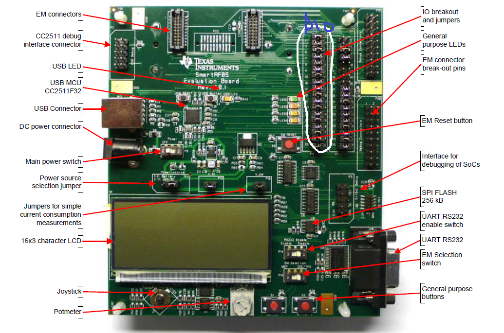 I have a slightly different debug board and a module with a chip.There are 2 buttons (+ reset) and 3 LEDs (+ power indicator) on the board. Here is one of them (D2) flashing when the firmware is working correctly.Having called the contacts, we determine the correspondence of pins, diodes and buttons:
- D1 - P10
- D2 - P11
- D3 - P14
- S2 - P20
- S1 - P01
So, HAL is a Hardware Abstraction Layer , a way to abstract from the implementation of equipment. The application code uses macros and functions that work with abstractions such as Button 1 or LED 2 , and the specific correspondence of abstractions and equipment is set separately.Let’s figure out what kind of HAL_LED_2 is and how to understand which pin it is suspended on. Bysearching, we find the hal_led.h file , where these constants and the HalLedSet function are described , where the LED number and mode are transmitted. Inside, the HalLedOnOff function is called to turn on and off the LED, which in turn executes either HAL_TURN_ON_LED2 orHAL_TURN_OFF_LED2 .HAL_TURN_ON_LED2 and HAL_TURN_OFF_LED2 are the macros described in hal_board_cfg.h . Macros change depending on the hardware configuration.In my case:#define HAL_TURN_OFF_LED2() st( LED2_SBIT = LED2_POLARITY (0); )
#define HAL_TURN_ON_LED2() st( LED2_SBIT = LED2_POLARITY (1); )
A little higher in the file are the correspondences of LED2_SBIT and LED2_POLARITY :
#define LED2_BV BV(1)
#define LED2_SBIT P1_1
#define LED2_DDR P1DIR
#define LED2_POLARITY ACTIVE_HIGH
This means that LED 2 is located on pin P1_1 and its switching level is high. But, judging by the code, the LED should go out when the button is pressed, but with us it remains on. If in this file hal_board_cfg.h we change:#define LED2_POLARITY ACTIVE_HIGH
on the#define LED2_POLARITY ACTIVE_LOW
then now the LED goes out when you press the S2 button, as it should be by logic.In order not to change common files that are not related to our application, it is better to do otherwise:- create a copy of the hal_board_cfg.h file (from the Z-Stack 3.0.2 \ Components \ hal \ target \ CC2530EB \ folder) in our Source folder and name it for example hal_board_cfg_DIYRuZRT.h
- let us make our copy of the file the very first one (thereby excluding the connection of the shared file). Create a preinclude.h file in our Source folder and write the line there:
#include "hal_board_cfg_DIYRuZRT.h"
- indicate the connection of this file is the very first - in the project settings:
$PROJ_DIR$\..\Source\preinclude.h
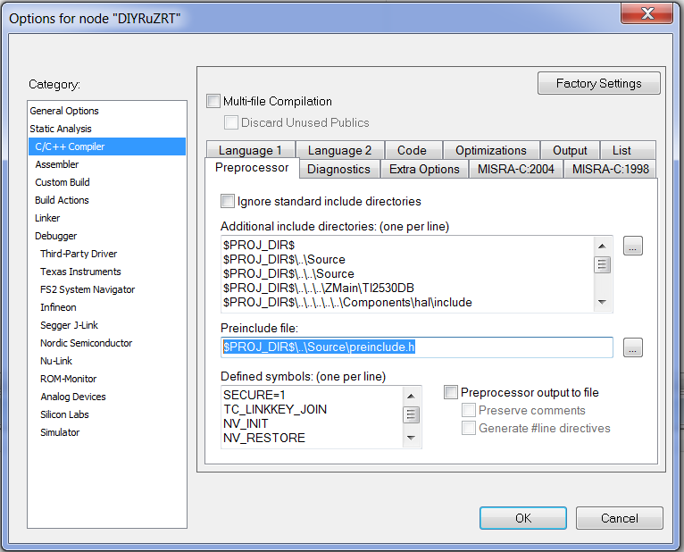 Now we can change the equipment parameters in our hal_board_cfg_DIYRuZRT.h file and in the preinclude.h file without having to edit shared files.I transferred the compiler directives to the same preinclude.h file and deleted them in the compiler Options:
#define SECURE 1
#define TC_LINKKEY_JOIN
#define NV_INIT
#define NV_RESTORE
#define xZTOOL_P1
#define xMT_TASK
#define xMT_APP_FUNC
#define xMT_SYS_FUNC
#define xMT_ZDO_FUNC
#define xMT_ZDO_MGMT
#define xMT_APP_CNF_FUNC
#define LEGACY_LCD_DEBUG
#define LCD_SUPPORTED DEBUG
#define MULTICAST_ENABLED FALSE
#define ZCL_READ
#define ZCL_WRITE
#define ZCL_BASIC
#define ZCL_IDENTIFY
#define ZCL_SCENES
#define ZCL_GROUPS
In the same file hal_board_cfg_DIYRuZRT.h we find the description of the S1 button and Joystick Center Press:
#define PUSH1_BV BV(1)
#define PUSH1_SBIT P0_1
#define PUSH2_BV BV(0)
#define PUSH2_SBIT P2_0
#define PUSH2_POLARITY ACTIVE_HIGH
This corresponds to the pins of the buttons on the board.Let's look at the hardware initialization - the HAL_BOARD_INIT macro in the same file. By default, the HAL_BOARD_CC2530EB_REV17 directive is turned on , so we look at the corresponding macro variant.
#if defined (HAL_BOARD_CC2530EB_REV17) && !defined (HAL_PA_LNA) && \
!defined (HAL_PA_LNA_CC2590) && !defined (HAL_PA_LNA_SE2431L) && \
!defined (HAL_PA_LNA_CC2592)
#define HAL_BOARD_INIT() \
{ \
uint16 i; \
\
SLEEPCMD &= ~OSC_PD; \
while (!(SLEEPSTA & XOSC_STB)); \
asm("NOP"); \
for (i=0; i<504; i++) asm("NOP"); \
CLKCONCMD = (CLKCONCMD_32MHZ | OSC_32KHZ); \
while (CLKCONSTA != (CLKCONCMD_32MHZ | OSC_32KHZ)); \
SLEEPCMD |= OSC_PD; \
\
\
PREFETCH_ENABLE(); \
\
HAL_TURN_OFF_LED1(); \
LED1_DDR |= LED1_BV; \
HAL_TURN_OFF_LED2(); \
LED2_DDR |= LED2_BV; \
HAL_TURN_OFF_LED3(); \
LED3_DDR |= LED3_BV; \
HAL_TURN_OFF_LED4(); \
LED4_SET_DIR(); \
\
\
P0INP |= PUSH2_BV; \
}
It is in this macro that the modes and registers of the processor are initialized.Instead LED2_DDR and others will be substituted P1DIR - register this port P1 , charge operation mode pins (input or output). Accordingly, LED2_BV is setting to 1 per bit of the corresponding pin (in our case, 1 bit, which corresponds to P1_1 pin ):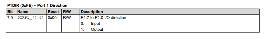 Registers and processor modes are described in the documentation of the“cc253x User's Guide”.But nowhere is it visible how the buttons are configured. Buttons are processed similarly, but in another file - hal_key.c . It defines the parameters of the buttons and functions HalKeyInit , HalKeyConfig, HalKeyRead , HalKeyPoll . These functions are responsible for initializing the subsystem of working with buttons and reading values.By default, button processing is performed on a timer every 100ms. Pin P2_0 for the current configuration is assigned to the joystick and its current state is read as a click - therefore, the LED blink timer starts.
6. We configure the device for ourselves
Change in the file zcl_DIYRuZRT.h :in the file OSAL_DIYRuZRT_data.c :- DIYRuZRT_DEVICE_VERSION at 1
- zclDIYRuZRT_ManufacturerName on {6, 'D', 'I', 'Y', 'R', 'u', 'Z'}
- zclDIYRuZRT_ModelId on {9, 'D', 'I', 'Y', 'R', 'u', 'Z', '_', 'R', 'T'}
- zclDIYRuZRT_DateCode on {8, '2', '0', '2', '0', '0', '4', '0', '5'}
In order for the device to be able to connect to the network on any channel (only 11 by default, specified in the DEFAULT_CHANLIST directive in the Tools \ f8wConfig.cfg file ), you must specify this feature in the preinclude.h file by changing the value of the directive.We also add the compilation directive DISABLE_GREENPOWER_BASIC_PROXY so that the GREENPOWER endpoint is not created for our device.Also turn off the unnecessary support for the LCD screen.
#define DISABLE_GREENPOWER_BASIC_PROXY
#define DEFAULT_CHANLIST 0x07FFF800
In order for our device to automatically try to connect to the network, we will add the connection to the network in the function code zclDIYRuZRT_Init .bdb_StartCommissioning(BDB_COMMISSIONING_MODE_NWK_STEERING |
BDB_COMMISSIONING_MODE_FINDING_BINDING);
After that, execute Build, fill the firmware into the chip and start pairing on the coordinator. I check the operation of the Zigbee network in ioBroker.zigbee, this is how the new connected device looks: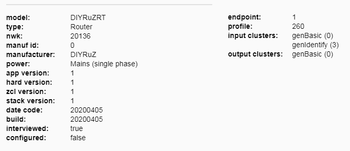 Great, it turned out to connect the device!
7. We complicate the operation of the device
Now let's try to adapt the functionality a bit:- The process of connecting the device to the network is done by a long press on the button.
- If the device was already on the network, then a long press displays it from the network.
- Short press - switches the status of the LED.
- The status of the LED should be maintained when the device starts after a power failure.
To set up my own button processing, I created the DIYRuZRT_HalKeyInit function similar to the one in the hal_key.c module , but exclusively for my set of buttons.
void DIYRuZRT_HalKeyInit( void )
{
halKeySavedKeys = 0;
PUSH1_SEL &= ~(PUSH1_BV);
PUSH1_DIR &= ~(PUSH1_BV);
PUSH1_ICTL &= ~(PUSH1_ICTLBIT);
PUSH1_IEN &= ~(PUSH1_IENBIT);
PUSH2_SEL &= ~(PUSH2_BV);
PUSH2_DIR &= ~(PUSH2_BV);
PUSH2_ICTL &= ~(PUSH2_ICTLBIT);
PUSH2_IEN &= ~(PUSH2_IENBIT);
}
Calling this function added to the macro HAL_BOARD_INIT file hal_board_cfg_DIYRuZRT.h . To avoid conflict, disable the built-in hal_key in the same file hal_board_cfg_DIYRuZRT.h :#define HAL_KEY FALSE
Because the standard button reader is disabled, we will do it ourselves.In the initialization function zclDIYRuZRT_Init , we start the timer for reading the states of the buttons. The timer will generate our HAL_KEY_EVENT event .osal_start_reload_timer( zclDIYRuZRT_TaskID, HAL_KEY_EVENT, 100);
And in the event loop, we will handle the HAL_KEY_EVENT event by calling the DIYRuZRT_HalKeyPoll function :
void DIYRuZRT_HalKeyPoll (void)
{
uint8 keys = 0;
if (HAL_PUSH_BUTTON1())
{
keys |= HAL_KEY_SW_1;
}
if (HAL_PUSH_BUTTON2())
{
keys |= HAL_KEY_SW_2;
}
if (keys == halKeySavedKeys)
{
return;
}
halKeySavedKeys = keys;
OnBoard_SendKeys(keys, HAL_KEY_STATE_NORMAL);
}
Saving the state of the buttons in the halKeySavedKeys variable allows us to determine the moment of change - pressing and releasing the buttons.When you click on the button, start the timer for 5 seconds. If this timer fires, the DIYRuZRT_EVT_LONG event will be generated . If the button is released, the timer is reset. In any case, if you press the button, we switch the status of the LED.
static void zclDIYRuZRT_HandleKeys( byte shift, byte keys )
{
if ( keys & HAL_KEY_SW_1 )
{
osal_start_timerEx(zclDIYRuZRT_TaskID, DIYRuZRT_EVT_LONG, 5000);
updateRelay(RELAY_STATE == 0);
}
else
{
osal_stop_timerEx(zclDIYRuZRT_TaskID, DIYRuZRT_EVT_LONG);
}
}
Now, when processing a long-press event, we pay attention to the current state of the network through the structure attribute bdbAttributes.bdbNodeIsOnANetwork
if ( events & DIYRuZRT_EVT_LONG )
{
if ( bdbAttributes.bdbNodeIsOnANetwork )
{
zclDIYRuZRT_LeaveNetwork();
}
else
{
bdb_StartCommissioning(
BDB_COMMISSIONING_MODE_NWK_FORMATION |
BDB_COMMISSIONING_MODE_NWK_STEERING |
BDB_COMMISSIONING_MODE_FINDING_BINDING |
BDB_COMMISSIONING_MODE_INITIATOR_TL
);
osal_start_timerEx(zclDIYRuZRT_TaskID, DIYRuZRT_EVT_BLINK, 500);
}
return ( events ^ DIYRuZRT_EVT_LONG );
}
We go further. The state of the LED will be saved in a variable, the value of which we will save in the NV-memory. When the device starts, we will read the value from memory into a variable.
if ( SUCCESS == osal_nv_item_init( NV_DIYRuZRT_RELAY_STATE_ID, 1, &RELAY_STATE ) ) {
osal_nv_read( NV_DIYRuZRT_RELAY_STATE_ID, 0, 1, &RELAY_STATE );
}
applyRelay();
void updateRelay ( bool value )
{
if (value) {
RELAY_STATE = 1;
} else {
RELAY_STATE = 0;
}
osal_nv_write(NV_DIYRuZRT_RELAY_STATE_ID, 0, 1, &RELAY_STATE);
applyRelay();
}
void applyRelay ( void )
{
if (RELAY_STATE == 0) {
HalLedSet ( HAL_LED_1, HAL_LED_MODE_OFF );
} else {
HalLedSet ( HAL_LED_1, HAL_LED_MODE_ON );
}
}
8. Now we will deal with Zigbee
So far we have sorted out the hardware - with the button we control the LED. Now we implement the same through Zigbee.To control the relay, it is enough for us to use our only endpoint and implement the GenOnOff cluster . We read the Zigbee Cluster Library specification for the GenOnOff cluster :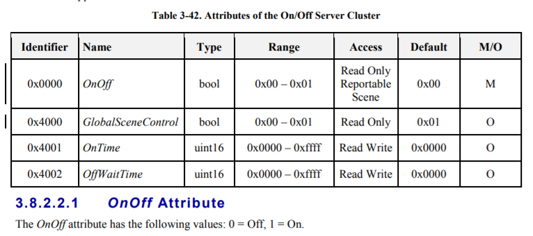
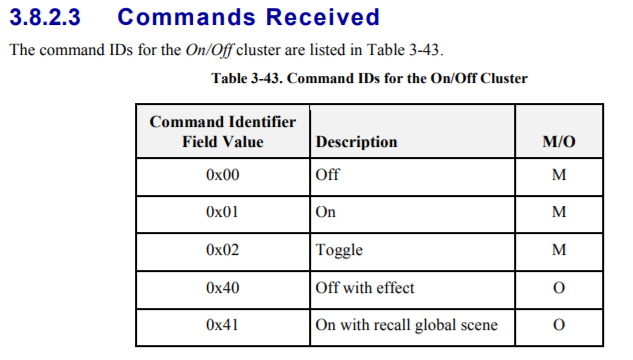 It is enough to implement the OnOff attribute and the On, Off, Toggle commands.First, add the directive to preinclude.h :
#define ZCL_ON_OFF
In the description of our attributes zclDIYRuZRT_Attrs we add new cluster attributes:
{
ZCL_CLUSTER_ID_GEN_ON_OFF,
{
ATTRID_ON_OFF,
ZCL_DATATYPE_BOOLEAN,
ACCESS_CONTROL_READ,
(void *)&RELAY_STATE
}
},
{
ZCL_CLUSTER_ID_GEN_ON_OFF,
{
ATTRID_CLUSTER_REVISION,
ZCL_DATATYPE_UINT16,
ACCESS_CONTROL_READ | ACCESS_CLIENT,
(void *)&zclDIYRuZRT_clusterRevision_all
}
},
We also add the cluster to the list of supported incoming endpoint clusters zclDIYRuZRT_InClusterList .To implement control commands, add a handler to the zclDIYRuZRT_CmdCallbacks table .
static zclGeneral_AppCallbacks_t zclDIYRuZRT_CmdCallbacks =
{
zclDIYRuZRT_BasicResetCB,
NULL,
zclDIYRuZRT_OnOffCB,
NULL,
NULL,
NULL,
#ifdef ZCL_LEVEL_CTRL
NULL,
NULL,
NULL,
NULL,
#endif
And we implement it:
static void zclDIYRuZRT_OnOffCB(uint8 cmd)
{
afIncomingMSGPacket_t *pPtr = zcl_getRawAFMsg();
zclDIYRuZRT_DstAddr.addr.shortAddr = pPtr->srcAddr.addr.shortAddr;
if (cmd == COMMAND_ON) {
updateRelay(TRUE);
}
else if (cmd == COMMAND_OFF) {
updateRelay(FALSE);
}
else if (cmd == COMMAND_TOGGLE) {
updateRelay(RELAY_STATE == 0);
}
}
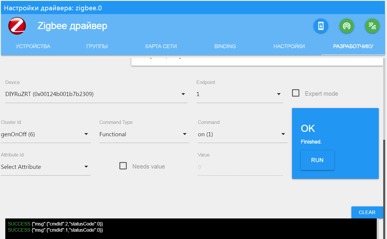
Great, now the relay can be switched by commands.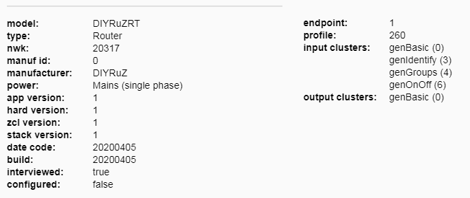
 But this is not enough. Now we must also inform the coordinator about the current state of the LED, if we switch it with the button.Again, add the directive:
#define ZCL_REPORTING_DEVICE
Now create a function zclDIYRuZRT_ReportOnOff that sends a status message. We will call it when the LED is switched and when the device starts.
void zclDIYRuZRT_ReportOnOff(void) {
const uint8 NUM_ATTRIBUTES = 1;
zclReportCmd_t *pReportCmd;
pReportCmd = osal_mem_alloc(sizeof(zclReportCmd_t) +
(NUM_ATTRIBUTES * sizeof(zclReport_t)));
if (pReportCmd != NULL) {
pReportCmd->numAttr = NUM_ATTRIBUTES;
pReportCmd->attrList[0].attrID = ATTRID_ON_OFF;
pReportCmd->attrList[0].dataType = ZCL_DATATYPE_BOOLEAN;
pReportCmd->attrList[0].attrData = (void *)(&RELAY_STATE);
zclDIYRuZRT_DstAddr.addrMode = (afAddrMode_t)Addr16Bit;
zclDIYRuZRT_DstAddr.addr.shortAddr = 0;
zclDIYRuZRT_DstAddr.endPoint = 1;
zcl_SendReportCmd(DIYRuZRT_ENDPOINT, &zclDIYRuZRT_DstAddr,
ZCL_CLUSTER_ID_GEN_ON_OFF, pReportCmd,
ZCL_FRAME_CLIENT_SERVER_DIR, false, SeqNum++);
}
osal_mem_free(pReportCmd);
}
Now in the logs we see messages about a change in the status of the LED.9. Connect the ds18b20 temperature sensor
The sensor is connected to any free pin (in my case, set P2_1 ).Add the sensor polling code to the application. We will interview regularly - once a minute.Immediately upon polling, the network coordinator will notify you of the current value.Read the ZCL specifications for sending data from temperature sensors. We need a clusterTemperature Measurement.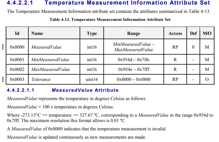 We see that we need to implement 3 attributes, one of which represents the temperature value multiplied by 100.Here we add the attributes by analogy with the GenOnOff cluster . The coordinator will be informed on the DIYRuZRT_REPORTING_EVT event , which we plan at the start once a minute. In the event handler, we will callzclDIYRuZRT_ReportTemp , which will read the temperature of the sensor and send a message.
void zclDIYRuZRT_ReportTemp( void )
{
zclDIYRuZRT_MeasuredValue = readTemperature();
const uint8 NUM_ATTRIBUTES = 1;
zclReportCmd_t *pReportCmd;
pReportCmd = osal_mem_alloc(sizeof(zclReportCmd_t) +
(NUM_ATTRIBUTES * sizeof(zclReport_t)));
if (pReportCmd != NULL) {
pReportCmd->numAttr = NUM_ATTRIBUTES;
pReportCmd->attrList[0].attrID = ATTRID_MS_TEMPERATURE_MEASURED_VALUE;
pReportCmd->attrList[0].dataType = ZCL_DATATYPE_INT16;
pReportCmd->attrList[0].attrData = (void *)(&zclDIYRuZRT_MeasuredValue);
zclDIYRuZRT_DstAddr.addrMode = (afAddrMode_t)Addr16Bit;
zclDIYRuZRT_DstAddr.addr.shortAddr = 0;
zclDIYRuZRT_DstAddr.endPoint = 1;
zcl_SendReportCmd(DIYRuZRT_ENDPOINT, &zclDIYRuZRT_DstAddr,
ZCL_CLUSTER_ID_MS_TEMPERATURE_MEASUREMENT, pReportCmd,
ZCL_FRAME_CLIENT_SERVER_DIR, false, SeqNum++);
}
osal_mem_free(pReportCmd);
}
10. Pour firmware into the device
To change devboard to Sonoff BASICZBR3, you need to adjust the matching of the LED pins and buttons.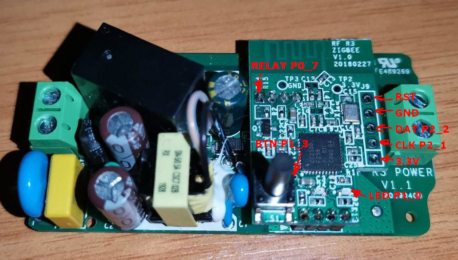 Redo LED 1 on pin P0_7 to control the relay. Inclusion is carried out by a high level of ACTIVE_HIGH . We re-hang the S1 button on pin P1_3 , and the information LED 2 on P1_0 . We leave the temperature sensor on pin P2_1 . We make all these changes in the hal_board_cfg_DIYRuZRT.h file . To select a configuration, we will make a separate directive HAL_SONOFF . If it is set, then the settings for Sonoff BASICZBR3 will be used, otherwise for devboard.
#ifdef HAL_SONOFF
#define LED1_BV BV(7)
#define LED1_SBIT P0_7
#define LED1_DDR P0DIR
#define LED1_POLARITY ACTIVE_HIGH
#define LED2_BV BV(0)
#define LED2_SBIT P1_0
#define LED2_DDR P1DIR
#define LED2_POLARITY ACTIVE_LOW
#else
#define LED1_BV BV(0)
#define LED1_SBIT P1_0
#define LED1_DDR P1DIR
#define LED1_POLARITY ACTIVE_LOW
#define LED2_BV BV(1)
#define LED2_SBIT P1_1
#define LED2_DDR P1DIR
#define LED2_POLARITY ACTIVE_LOW
#endif
Another important parameter had to be corrected - the presence of "watch" quartz, because On the Sonoff BASICZBR3 board it is not soldered:
#define OSC32K_CRYSTAL_INSTALLED FALSE
Without these options, the firmware does not start (or rather, not always).After that, we collect the firmware and connect to the firmware.ATTENTION!!! Disconnect the Sonoff BASICZBR3 relay from the AC power before any connection and firmware!
We connect Sonoff BASICZBR3 wiring with CCDebugger, erase the chip and flash our firmware.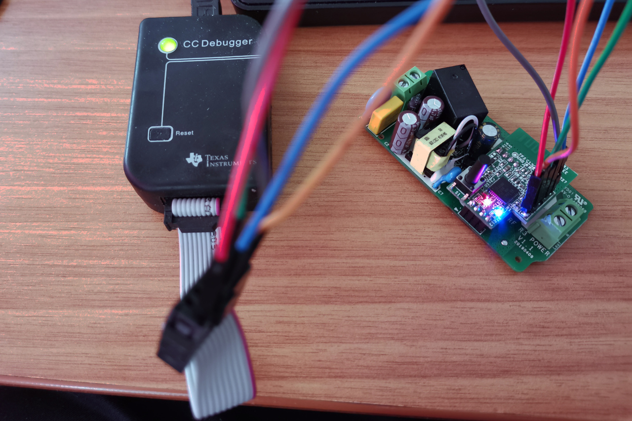
11. We start the device in zigbee2mqtt and ioBroker.Zigbee
Although the device we have appeared in the list of connected devices and we can manage it by sending commands, but we need to do this more correctly - with pictures and states.To get a new device in ioBroker.Zigbee , you need to perform 2 steps:- zigbee-herdsman-converters. , zigbee2mqtt.
- ioBroker.Zigbee
All changes can be made first in local files, and then done PR in the corresponding repositories.We find the location of the zigbee-herdsman-converters package in the installed ioBroker (or zigbee2mqtt). Inside the package we find the devices.js file https://github.com/Koenkk/zigbee-herdsman-converters/blob/master/devices.jsThis file contains descriptions of all the devices that ioBroker.zigbee and zigbee2mqtt can work with . We find in it a block of descriptions of DIYRuZ devices (after 2300 lines). Add a description of the new device to this block: {
zigbeeModel: ['DIYRuZ_RT'],
model: 'DIYRuZ_RT',
vendor: 'DIYRuZ',
description: '',
supports: 'on/off, temperature',
fromZigbee: [fz.on_off, fz.temperature],
toZigbee: [tz.on_off],
},
In the fromZigbee attribute , we specify the converters that will process messages coming from the device. Our two posts are standardized. The fz.on_off converter processes the on / off message, and fz.temperature processes the temperature data. The code of these converters (located in the file converters / fromZigbee.js) shows how incoming messages are processed and that the temperature is divided by 100. on_off: {
cluster: 'genOnOff',
type: ['attributeReport', 'readResponse'],
convert: (model, msg, publish, options, meta) => {
if (msg.data.hasOwnProperty('onOff')) {
const property = getProperty('state', msg, model);
return {[property]: msg.data['onOff'] === 1 ? 'ON' : 'OFF'};
}
},
},
 temperature: {
        cluster: 'msTemperatureMeasurement',
        type: ['attributeReport', 'readResponse'],
        convert: (model, msg, publish, options, meta) => {
            const temperature = parseFloat(msg.data['measuredValue']) / 100.0;
            return {temperature: calibrateAndPrecisionRoundOptions(temperature, options, 'temperature')};
        },
    },
In the toZigbee attribute, we specify the converters that will process our commands to the device. In our case, it is the tz.on_off converter for switching relays.Everything added to the "converters". Who uses zigbee2mqtt - you can already use it.And ioBroker users still add a description of the device to the ioBroker.zigbee \ lib \ devices.js file {
vendor: 'DIYRuZ',
models: ['DIYRuZ_RT'],
icon: 'img/DIYRuZ.png',
states: [
states.state,
states.temperature,
],
},
It is enough to indicate exactly the same model, a file with a picture and a list of states. In our case, the states are also standard: state for the state of the relay, temperature for displaying temperature values.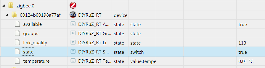
12. What next?
Unfortunately, I could not figure out all the aspects and features that Z-Stack 3.0 provides. Most likely I didn’t even correctly implement some kind of functionality or some built-in mechanisms could be used to implement it.Therefore, the above solution can be improved and developed. Here are some directions:- I could not quickly find solutions for the possibility of connecting child devices via relays. Other router devices can execute the permit_join command and connect new devices through themselves, without having to bring the new device to the coordinator. The device is represented by a router, it is correctly displayed on the network map, but refuses to execute the “permit_join” command. More precisely, the command executes, but the devices do not connect through it.
- Also, did not implement correct reporting. This is a way to configure status notification when you can use the configReport command to specify a list of attributes to send and the frequency of notification.
- Work with groups.
- Deal with interrupts and implement polling buttons through interrupts.
Well, for the following devices you need to deal with power modes and the creation of "sleeping" devices on batteries.As always, in addition to comments, I invite you to discuss this and other devices in Telegram chat on Zigbee .
I want to express my gratitude for the support and assistance in the development of my colleagues in the Telegram chat and Zigbee community:
References
The main documentation is included in the Z-Stack 3.0.2 SDK and is installed with it. But I will give part of the links here: