How can a design engineer feel the power of a geometric core? He works in his CAD-system and does not see its mathematical “stuffing”. Today we will show an example of how a user of the KOMPAS-3D system, in which three-dimensional modeling is based on the C3D core, turned directly to mathematicians and ordered a surface refinement necessary for designing the nose of the amphibious aircraft fuselage. And mathematicians fulfilled his order.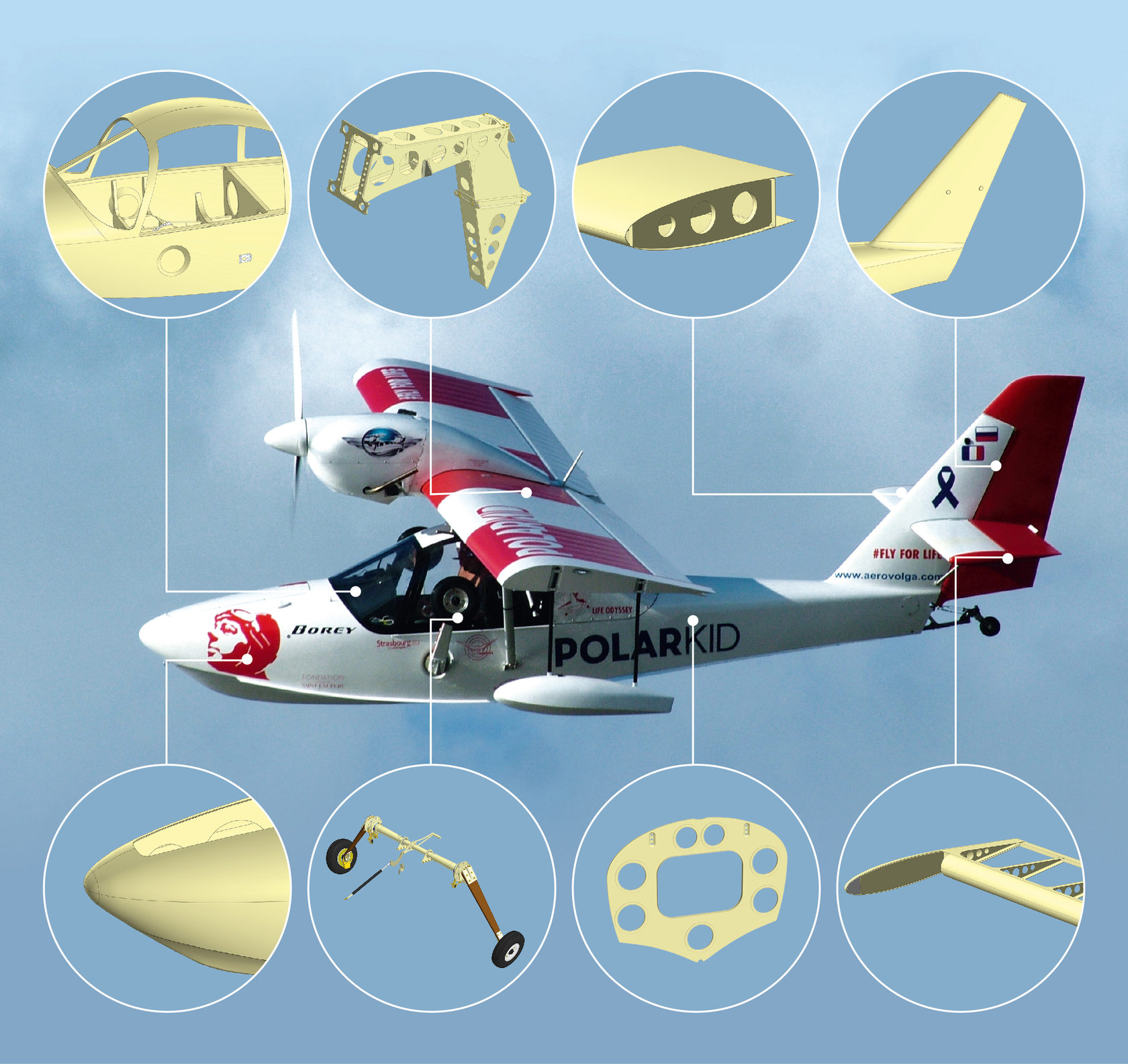 This is how the terms of reference were set. On air - Dmitry Suslakov, chief designer of the AeroVolga NPO.Translated into the language of geometric modeling, the AeroVolga’s proposal concerned the refinement of the surface by sections
 MbLoftedSurface, namely, the construction of surfaces where one or both end sections are represented by points with the ability to orient the normal in point sections, and in these areas it is necessary to ensure surface smoothness. Such an option when constructing a surface by sections, we called the "Dome".Since the surface MbLoftedSurfacebetween the sections varies according to the law of the composite spline of Hermite, to construct the dome at the end you need to set the vector of the derivativeat the end of the spline of the orthogonally selected normal. Normal is defined as axisin the local coordinate system of a point section. To determine the vector points on adjacent curves are entered , and the center of gravity of the cross section (fig. 1). The derivative vector can be written as:
Where Is the unit vector from the center of the section at , Is a certain coefficient.Coefficient is found from the condition of equality of the projection of the vector and to the selected normal :
 Fig. 1. Dome construction scheme.To control the smoothness of the transition, a coefficient is introduced.and is associated with the distance between points in adjacent sections. With smoothness control, the formula for the direction at the end looks like this:
The result of varying the smoothness coefficient is shown in Figure 2. Figure 2. Change in the smoothness coefficientDerivatives calculated by simple replacement , on the , and , respectively to obtain , taking into account where - derivatives of adjacent curves at selected points. Given the chosen directionand its derivatives, the smoothness of the surface near the top of the dome is shown in Figure 3.
 Figure 3. The zebra of the smoothness of the surface in sections near a point section Theboundary condition “Dome” can also be used to construct a body where intermediate sections are represented by compound contours (see Fig. 4). For this, it is necessary to determine the vector in the center of gravity of the section . However, in the general case, the direction can be arbitrary.
 Fig. 4. A body with mating surfaces with the boundary condition “Dome”.With a significant deviation of the vectorfrom its basic definition, the behavior of the resulting body can change qualitatively - from a smooth transition in a point cross section to a pointed peak (Fig. 5). In this case, the condition for determining the normal at the end will be maintained.
 Fig. 5. Dome change with different vector definitionIn the structure of the boundary conditions for the surface along the family of curves, there are three fields responsible for constructing a domed surface:
setNormal - a flag for calculating the direction of the surface at the end from the condition for specifying the normal at the end,derFactor - smoothness coefficient at the end,directSurf - direction of the vector
The fields for constructing the surface in sections with the installation of the normal at the end are set using a special constructor MbLoftedSurface.The proposed tool is a new solution that allows the engineer to simulate smooth contours of the product based on design, aerohydrodynamic and other design requirements., -3D:
«, «», , – , , , , .
, – ? , , ? , « ».
At some point, the message “In the core, the functionality is ready!” Arrives. Now the conceived implementation in KOMPAS begins, and then you can experience what has been done. In this case, a fine-tuning was done to obtain a smooth geometry without sharp changes in curvature, which can be seen in the illustration with a zebra. The effect on other methods of constructing the operation "Element by sections" was also tested.
In the experimental assembly of KOMPAS, the functionality was demonstrated to experts from the aviation industry, after which there were final refinements on form management (coefficient), and now we can present what has been done to everyone who starts work in KOMPAS-3D v19. ”
 Posted by Vitaliy Shaposhnikov, C3D Labs Mathematician and Programmer