 Good day, friends!This article explains some concepts from the theory of music that the Web Audio API (WAA) operates on. Knowing these concepts, you can make informed decisions when designing audio in an application. This article will not make you an experienced sound engineer, but it will help you understand why WAA works the way it works.
Audio circuit
The essence of WAA is to perform some operations with sound within an audio context. This API has been specifically designed for modular routing. The basic operations with sound are audio nodes, interconnected and forming a routing diagram (audio routing graph). Several sources - with different types of channels - are processed within a single context. This modular design provides the necessary flexibility to create complex functions with dynamic effects.Audio nodes are interconnected through inputs and outputs, form a chain that starts from one or more sources, passes through one or more nodes, and ends at the destination. In principle, you can do without a destination, for example, if we just want to visualize some audio data. A typical web audio workflow looks something like this:- Create an audio context
- Inside the context, create sources - such as <audio>, an oscillator (sound generator) or stream
- Create effect nodes such as reverb , biquad filter, panner or compressor
- Select a destination for audio, such as speakers on a user's computer
- Establish a connection between sources through effects to a destination

Channel designation
The number of available audio channels is often indicated in numerical format, for example, 2.0 or 5.1. This is called the channel designation. The first digit indicates the full range of frequencies that the signal includes. The second digit indicates the number of channels reserved for the low-frequency effect outputs - subwoofers .Each input or output consists of one or more channels built according to a certain audio circuit. There are various discrete channel structures such as mono, stereo, quad, 5.1, etc.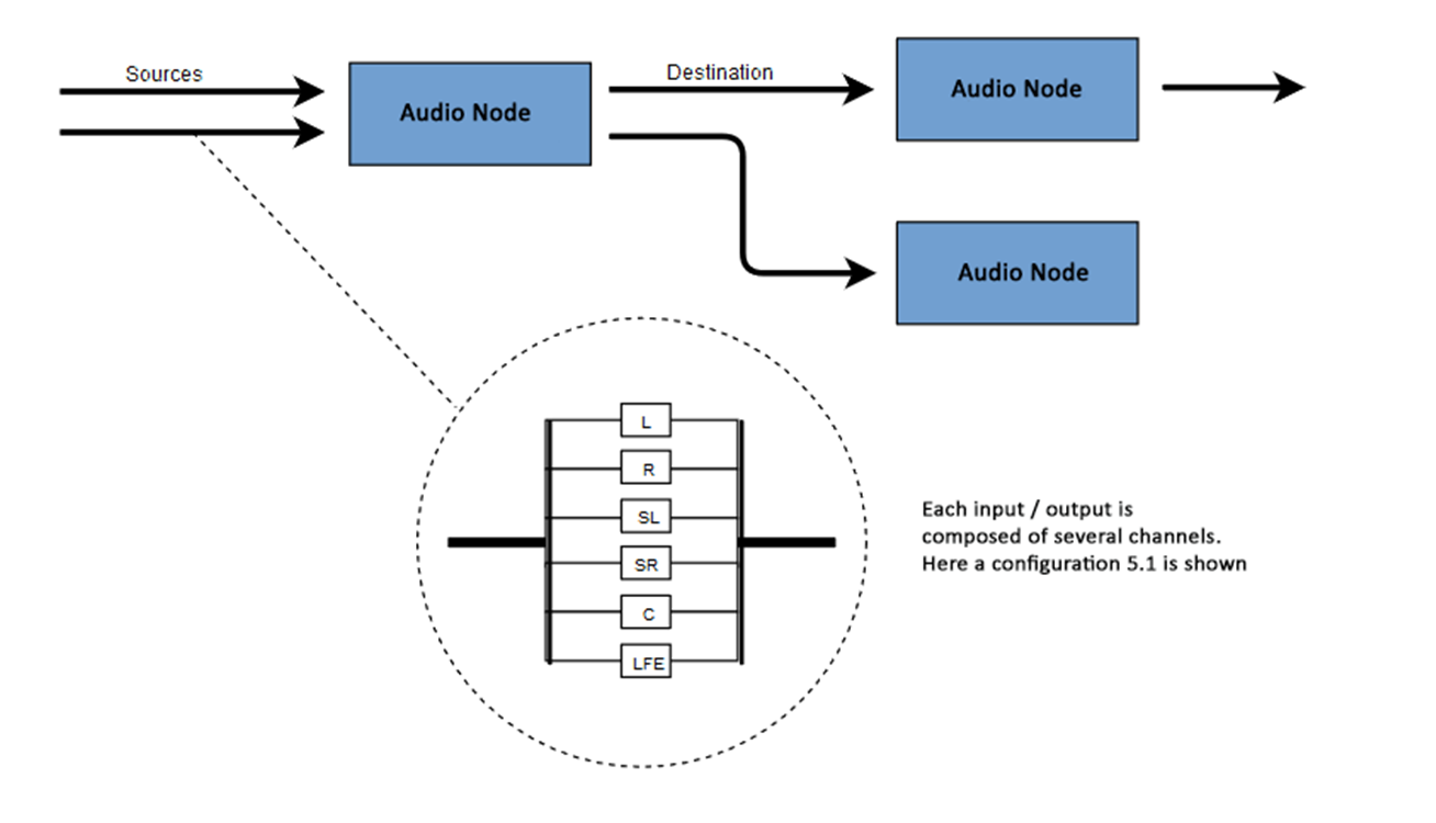 Audio sources can be obtained in many ways. The sound may be:
- Generated by JavaScript through an audio node (such as an oscillator)
- Created from raw data using PCM (Pulse Code Modulation)
- Derived from HTML media elements (such as <video> or <audio>)
- Derived from a WebRTC media stream (such as a webcam or microphone)
Audio data: what is in the sample
Sampling means converting a continuous signal into a discrete (divided) (analog to digital) signal. In other words, a continuous sound wave, such as a live concert, is converted into a sequence of samples, which allows the computer to process the audio in separate blocks.Audio Buffer: Frames, Samples, and Channels
AudioBuffer accepts the number of channels as parameters (1 for mono, 2 for stereo, etc.), length - the number of sample frames inside the buffer, and sampling frequency - the number of frames per second.A sample is a simple 32-bit floating-point value (float32), which is the value of the audio stream at a particular point in time and in a particular channel (left or right, etc.). A sample frame or frame is a set of values of all channels reproduced at a certain point in time: all samples of all channels reproduced at the same time (two for stereo, six for 5.1, etc.).The sampling rate is the number of samples (or frames, since all samples in a frame are played at one time), played back in one second, measured in hertz (Hz). The higher the frequency, the better the sound quality.Let's look at mono and stereo buffers, each one second long, reproduced at a frequency of 44100 Hz:- Mono buffer will have 44100 samples and 44100 frames. The value of the “length” property is 44100
- The stereo buffer will have 88,200 samples, but also 44,100 frames. The value of the “length” property will be 44100 - the length is equal to the number of frames
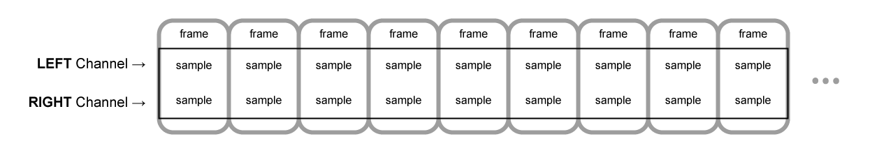 When the playback of the buffer begins, we first hear the leftmost frame of the sample, then the nearest right frame, etc. In the case of stereo, we hear both channels simultaneously. Sample frames are independent of the number of channels and provide the opportunity for very accurate audio processing.Note: to get the time in seconds from the number of frames, it is necessary to divide the number of frames by the sampling rate. To get the number of frames from the number of samples, divide the latter by the number of channels.Example:
let context = new AudioContext()
let buffer = context.createBuffer(2, 22050, 44100)
Note: in digital audio, 44100 Hz or 44.1 kHz is the standard sampling frequency. But why 44.1 kHz?Firstly, because the range of audible frequencies (frequencies distinguishable by the human ear) varies from 20 to 20,000 Hz. According to Kotelnikov’s theorem, the sampling frequency should more than double the highest frequency in the signal spectrum. Therefore, the sampling frequency should be greater than 40 kHz.Secondly, the signals must be filtered using a low-pass filter.before sampling, otherwise there will be an overlap of spectral “tails” (frequency swapping, frequency masking, aliasing) and the shape of the reconstructed signal will be distorted. Ideally, a low-pass filter should pass frequencies below 20 kHz (without attenuation) and drop frequencies above 20 kHz. In practice, some transition band is required (between the passband and the suppression band), where the frequencies are partially attenuated. An easier and more economical way to do this is to use an anti-change filter. For a sampling frequency of 44.1 kHz, the transition band is 2.05 kHz.In the above example, we get a stereo buffer with two channels, reproduced in an audio context with a frequency of 44100 Hz (standard), 0.5 second long (22050 frames / 44100 Hz = 0.5 s).let context = new AudioContext()
let buffer = context.createBuffer(1, 22050, 22050)
In this case, we get a mono buffer with one channel, reproduced in an audio context with a frequency of 44100 Hz, it will oversampling to 44100 Hz (and increasing the frames to 44100), 1 second long (44100 frames / 44100 Hz = 1 s).Note: Audio resampling (“resampling”) is very similar to resizing (“resizing”) images. Suppose we have a 16x16 image, but we want to fill this area with a 32x32 size. We do resizing. The result will be less quality (it may be blurry or torn depending on the zoom algorithm), but it works. Resampled audio is the same thing: we save space, but in practice it’s unlikely to achieve high quality sound.Planar and Striped Buffers
WAA uses a planar buffer format. The left and right channels interact as follows:LLLLLLLLLLLLLLLLRRRRRRRRRRRRRRRR ( , 16 )
In this case, each channel works independently of the others.An alternative is to use an alternating format:LRLRLRLRLRLRLRLRLRLRLRLRLRLRLRLR ( , 16 )
This format is often used for MP3 decoding.WAA uses only the planar format, as it is better suited for sound processing. The planar format is converted to alternating when data is sent to the sound card for playback. When decoding MP3s, the inverse is converted.Audio channels
Different buffers contain a different number of channels: from simple mono (one channel) and stereo (left and right channels) to more complex sets, such as quad and 5.1 with a different number of samples in each channel, which provides a richer (richer) sound. Channels are usually represented by abbreviations:Up-mixing and down-mixing
When the number of channels at the input and output does not match, apply mixing up or down. Mixing is controlled by the AudioNode.channelInterpretation property:Visualization
Visualization is based on receiving output audio data, such as data on amplitude or frequency, and their subsequent processing using any graphic technology. WAA has an AnalyzerNode that does not distort the signal passing through it. At the same time, it is able to extract data from audio and transfer it further, for example, to & ltcanvas>.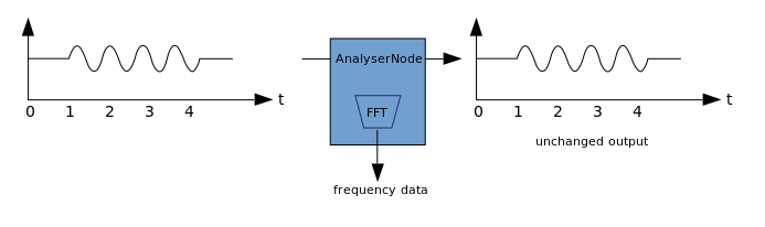 The following methods can be used to extract data:
- AnalyzerNode.getFloatByteFrequencyData () - copies the current frequency data to the Float32Array
- AnalyzerNode.getByteFrequencyData () - copies the current frequency data to a Uint8Array (unsigned byte array)
- AnalyserNode.getFloatTimeDomainData() — Float32Array
- AnalyserNode.getByteTimeDomainData() — Uint8Array
Audio spatialization (processed by PannerNode and AudioListener) allows you to simulate the position and direction of the signal at a specific point in space, as well as the position of the listener.The position of the panner is described using right-handed Cartesian coordinates; for motion, the velocity vector necessary to create the Doppler effect is used ; for direction, the directivity cone is used. This cone can be very large in the case of multidirectional sound sources. The position of the listener is described as follows: movement - using the velocity vector, the direction where the head of the listener is - using two directional vectors, front and top. Snapping is done to the top of the head and nose of the listener at right angles.
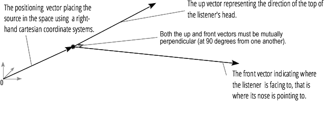
Junction and branching
A connection describes a process in which a ChannelMergerNode receives several input mono sources and combines them into a single multi-channel output signal.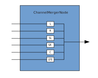 Branching is the reverse process (implemented through ChannelSplitterNode).
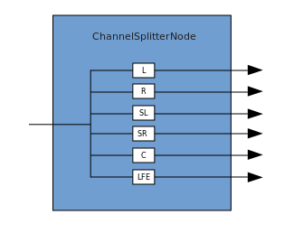 An example of working with WAA can be found here . The source code for the example is here . Here's an article about how it all works.Thank you for attention.