Continuation of the project to replace the Toyota Prius media system.In this article - PHY, Transport, and packet delivery to the host device, which finally managed to be verified on the real native head of the Prius.Quickly the fairy tale affects, but not quickly the thing is done. Today I continue the protracted project on redesigning the media system in Prius, which began 2 years ago.Historical Offtopic— USB-AVC , . , , .. ++ — , .
, , , , .
, , , PHY- .
So, from the very beginning. Digging around on the Internet for adapters to AVC-LAN, I very often saw solutions similar to this . And in the discussion, such comments often slip through:Honestly, it doesn’t work very well, or rather it doesn’t work well with all heads.
While the tire is perfectly readable on some old radio with a 99 year old Spacio.
I was initially fundamentally opposed to doing something, and solutions with structurally instability do not suit me.We will repeat the path of reverse engineering of the tire. Go.First of all, we connect to the bus on a live car, and remove the waveform: The beginning of the pack.
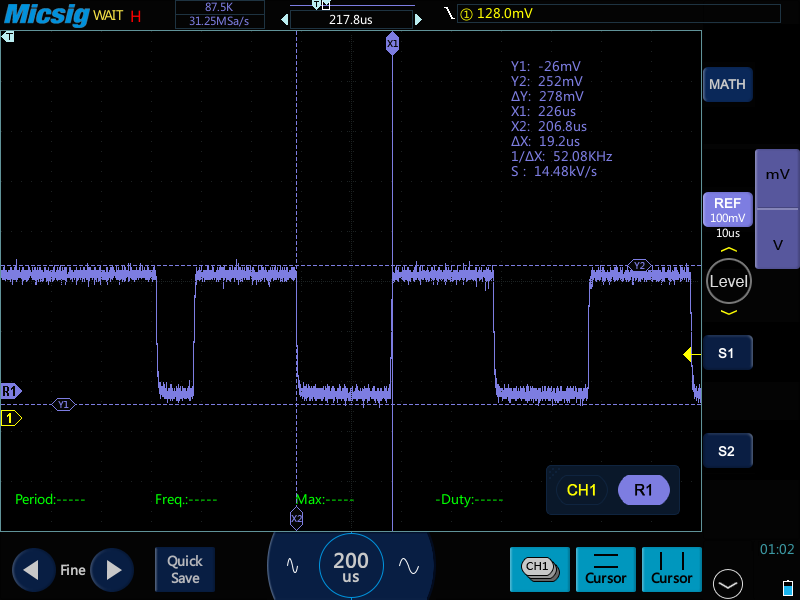 Bits are somewhere in the middle, larger.
 Something very similar to ACK.A little more about this strange step - below.I already made screenshots of the waveforms from the stored data, while taking it, I did not immediately pay attention to the voltage range in which I took the data. And when he drew it, he had to get down into the car again to make sure that he had not survived from the mind. Yes, the span of the differential bus is only 200mV (!!!).Next we go to the datasheet used by colleagues ST485, and we see the following there:
 Here, in fact, the root of all the troubles was found, because of which we have to play with resistors, and pray to the rosin gods so that the converter works on a specific machine. Work near thresholds is evil. But even more interesting is that for AVC-LAN, which in its physics is a clone of some IE-Bus from NEC, according to its specification (the link will be a bit further), the active state is voltage above 120mV, while ST485 has the right to consider anything less than 200mV is zero. Well, that is, if, due to manufacturing deviations, the ST485 has a threshold level slightly lower, and appears on the bus for margin slightly above the norm (up to 6 volts is allowed), then, of course, ST485 will be able to receive such a signal. And these manufacturing inaccuracies are the only thing that forces devices with ST485 in the composition sometimeswork. Of course, we will not lay such happiness in development.The second available solution based on the same ST485 and an operational amplifier, I did not like the abundance of components. Well, in the 21st century we live, after all.Solution:There are special converters for AVC-LAN. But I was not able to get them at an affordable price for this device. Brotherly China again came to the rescue, where the HA12240FP was discovered , which has a voltage difference for perceiving a log. “1” by datasheet is 80..110 mV. This will allow our tire to set an active level with an almost double margin. Arranges.We give birth to the scheme on the STM32F103 mentioned in the first part:
 UPD: The scheme was born in a hurry, it contains an error. Bus drivers must be powered from 5V. If so, as in the diagram, their differential rises. threshold, and not all packets are accepted.Everything is simple to primitivism, I think, does not need a description. Except, perhaps, the fact that the choice of legs for RX1 / 2 is not accidental, and the first version of the circuit required “file refinement” in order to get signals to the capture / comparison inputs, because I want to use it to measure the pulse length. Alternative solutions - polling and interrupt on state change lose in accuracy and complexity of software implementation. Plus - I would like to receive at least two lines in parallel (there are three in the head), and if the fronts coincide on two, you can say goodbye to the idea of any acceptable accuracy if you do not use capture / comparison.Further analysis of the data in the package is well-written here . But, given that links are inconsistent, I will briefly repeat here:
- The differential bus, here they write about the interpretation of the levels of the log. "1" at <20mV, log. "0" -> 110mV.
- The bit length is 40 µs, the first 20 µs is always “0”, the last 7 µs is always “1”, in the middle is the bit value.

Well, the traffic light:
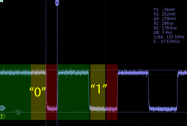
- Start bit - longer than 180 μs
- (ACK). «», - :

ACK- , Dallas 1-wire, , , , . , . 1 , «0» ( , ), .2 , , , . .3 , (1), , , 7 , . «1».
Well ... we figured out the physical level, drew the circuit, and got the board apart. It turned out something like this: The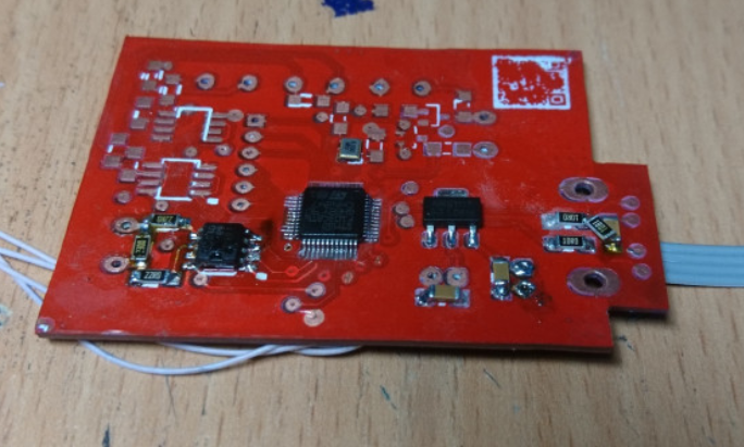
 printed circuit board came out somewhat unsuccessfully, and not because the QR code did not work in silk-screen printing. There is an error in the circuit in it (in the diagram above I already corrected it) regarding the selection of legs for the RX, and three line drivers are divorced. In the process of writing and debugging the program, I realized that it’s good if you can run at least two steadily. Yes, and more is not necessary.Well ... the device turned out to be simple and effective, while the constructive problem with the mismatch of levels has been resolved.Further in the program:
- . , . : * USB — , , «» . . * , 8, 6- , 4.4 . , , .
- Android monitor for complete reverse of the bus logic. If someone is strong in Android and Kotlin, I will be grateful for the opportunity to consult. These are timid attempts to master everything at once, therefore do not enter the repository by reference without a new pass :)
UPD: fixed temporal s e data instead microseconds were ms.