Greetings to all readers of Habr! Today I want to share with you my new project - a wireless soil moisture sensor, which is built on the basis of the well-known soil moisture module with aliexpress. The new sensor is a logical continuation of my first DIY project on this topic. But in the new implementation, this is no longer an arduino module, but a complete device with its own case. So, porridge from the ax, part two! :)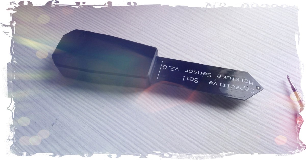 The Chinese soil moisture measurement module is built on a 555 timer. The measurement method is capacitive. For my project, I needed a version of the module with the XC6206P332 voltage regulator installed at 3.3V, which in the future will have to be removed from the module board. The fact is that in such versions we use a modification of the TLC555 timer with a lower threshold for power supply of 2V. In versions without a stabilizer, NE555 timers are used with a lower power threshold of 5V. But in any case, what is easier to buy for repeating this project is a repeater's business. In the first option, we solder the voltage regulator, in the second we change the timer, for example to one like this - LMC555 ( datasheet) working even from 1.5V. For the wireless module to the Chinese soil moisture sensor, I chose a radio module from EBYTE E73C on which the nRF52840 chip is installed. The argument was the price of the module and the available amount of these modules in my reserves.
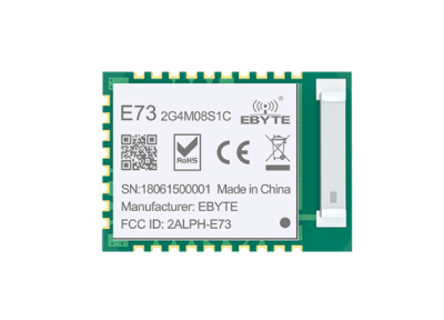 The wireless module turned out to be very simple, RGB LED, a couple of buttons, a field effect transistor, a battery. Even the most inexperienced beginner solder can assemble such a device. On the humidity sensor, in addition to removing the voltage stabilizer, it is also necessary to unsolder the connector and solder the 3P male plug in its place, step 2.54 mm.The dimensions of the board turned out to be slightly smaller than in the first project - 42x29mm, determined by the size of the battery holder.
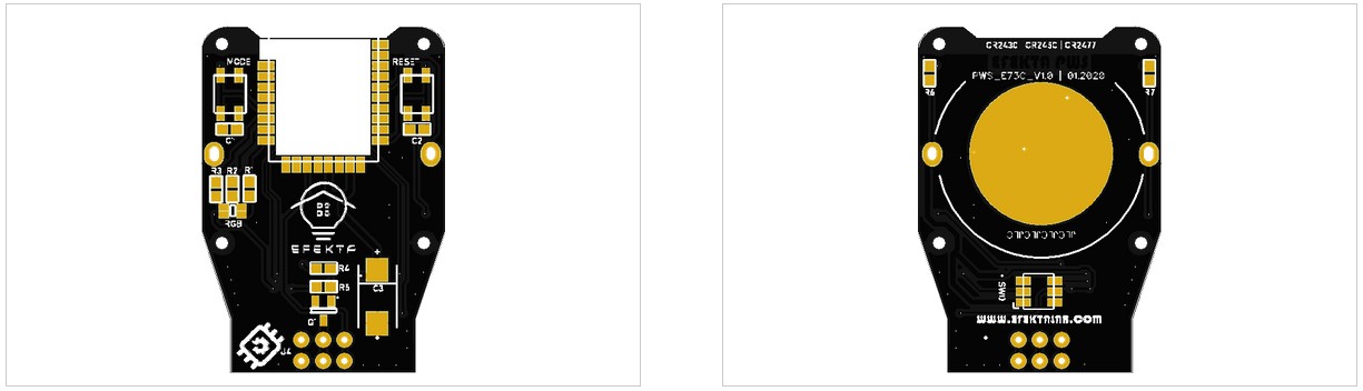 The case was printed on my ANYCUBIC household SLA printer. The printing time for parts is about a couple of hours. Subsequent post processing took about half an hour. The cost of spent polymer resin is ~ 100r.Consumption in sleep mode - 4.7mA, in transmission mode 8mA. The measurement interval is variable, step 1 minute. Measurement time 50ms (5 measurements in the test program), consumption during measurement ~ 1 mA. It also measures the temperature of the chip, measures the battery level. Data transfer to the UD controller through the Mysensors network, data transfer to the UD controller through the Zigbee network.The code of the test programs is on my Github.Example of working in the Mysensors network and the Mazhordomo UD.
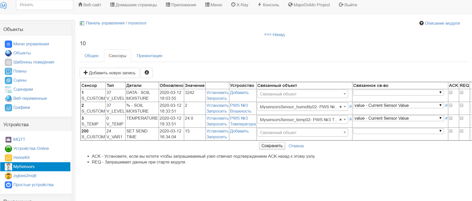
 Example of working on the ZigBee network and the Mazhordomo UD
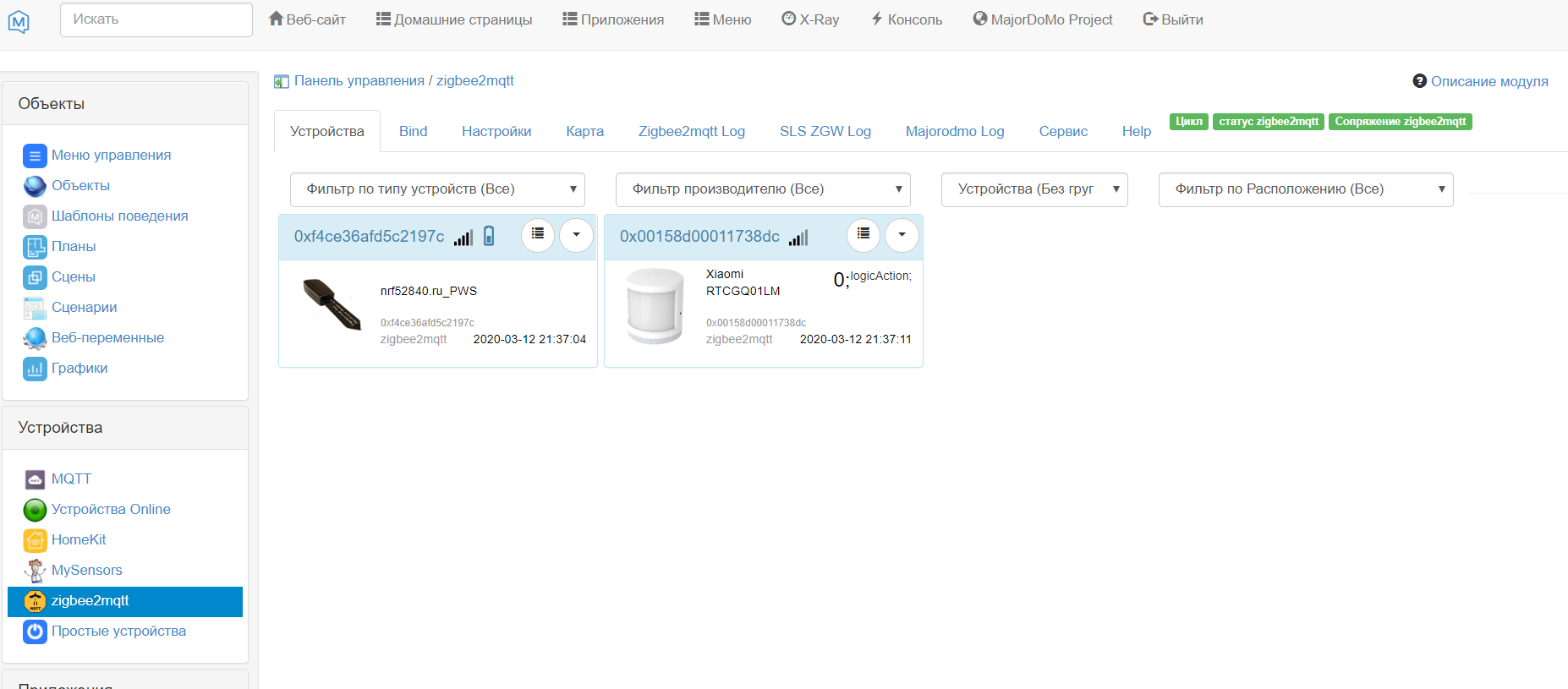
 The converter configuration code in the zigbee2mqtt module for the humidity sensor (not sure yet that this is the right solution).
{
        zigbeeModel: ['nrf52840.ru_PWS'],
        model: 'nrf52840.ru_PWS',
        vendor: 'nrf52840.ru',
        description: 'Plant watering sensor',
        supports: 'humidity',
		fromZigbee: [fz.humidity2, fz.battery_PWS],
        toZigbee: [],
		meta: {configureKey: 1},
        configure: async (device, coordinatorEndpoint) => {
            const endpoint = device.getEndpoint(10);
			await bind(endpoint, coordinatorEndpoint, ['msRelativeHumidity', 'genPowerCfg']);
            await configureReporting.humidity(endpoint);
			await configureReporting.batteryVoltage(endpoint);
        },
    },
 Test firmware was written by one of the participants in our DIY community - Lenz, here is his GIthub .The cost of the components that had to be added to the Chinese moisture meter was about 400-500 rubles. In my opinion it’s quite good.Sensor operation videoFurther plans for this project. I would like to replace the MK with something simpler, for example, with nRF52810 or nRF52811, but everything will depend on the price, most likely you will have to abandon the radio modules and just make it on a chip. Perhaps I’ll think about adding a buzzer, it’s very likely the power stabilizer, since now you need to take into account the supply voltage when measuring. Bring the Zigbee version to a stable state, make the BLE version, make a mobile display application. In general, there will definitely be something else.Github of this project .If you are interested in this project, I propose to go to the telegram group, there will always be assistance in mastering the Maysensors, Zigbee, BLE protocol on nRF5, they will help to master nRF52 programming in Arduino IDE and not only in it.Cart Chat - @DIY Devices.Cart Chat - @MySensors .