The simplest set of 433 MHz ISM receiver and transmitter has earned well-deserved popularity among electronics lovers. The kits are cheap (even in Chip-Deep you can buy them for 300 rubles, and on Ali, they say, generally for a fifty dollars), they are simple and reliable. In addition (which you probably do not suspect), this is the most long-range and penetrating method of wireless data exchange - a signal at a frequency of 433 MHz passes much better through obstacles and operates at a farther distance than in the popular 2.4 GHz band (433 MHz is completely delayed by a wall of half a meter of concrete, and Wi-Fi is already dying by 10 centimeters). I admit that recently appeared MBee-868 modulesBeing equipped with an appropriate (directional) antenna, they “shoot” further, but they are at least an order of magnitude more expensive, more difficult to connect, require energy-saving management and pre-configuration. And in addition, the frequency of 868 MHz passes through obstacles twice as bad (although, of course, it is incomparably better than the frequency of 2.4 GHz).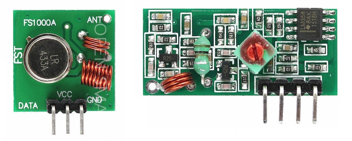 A lot has been written about 433 MHz transmitters and receivers (including on the hub) , of course. However, it seems that no one knows how to correctly include this kit in the circuit for some strange reason. When I once again read here that the kit “ took on 8 meters within line of sight, the 9th meter could not be mastered", My patience snapped. What other 8 meters ?! At 40-50 I would have believed, although in reality, probably, the range is even greater.It is worth noting that I further solve the problem of creating a line for transferring arbitrary data, and not just controlling any smart sockets or motor model boats. My task is more complicated, but still the distance of reliable operation is much greater. Moreover, in such a task it is important not only and not so much the distance within the line of sight (it can serve only for comparison), but the ability to penetrate various obstacles.My kit works out of town at a distance of about 25-30 meters at an acute angle to the log wall, so that approximately one meter (in total) of walls and partitions, partially shielded by foil insulation, is in the signal path. At a much shorter distance, almost directly behind the wall, WiFi is already completely losing signal. In the city, the signal finishes from one end of a three-room city apartment to the other through two interior partitions, as well as from the balcony, where in a straight line between the transmitter and receiver at least 80 centimeters of brickwork and a plaster partition. I did not use any more expensive kit options mentioned in the above review.An additional plus of the kit is that in pauses the transmitter does not consume anything, and without any special Sleep modes, simply by the principle of its device (the consumption current at rest is comparable to the collector leakage currents of a locked transistor, that is, about 100 nA).Let's see what the pitfalls are.
Transmitter Connection
The transmitter (it is called FS1000A), as we see from its diagram below, is the simplest generator based on a 433 MHz SAW resonator. The generator is assembled on transistor Q1, and the transistor Q2, on the basis of which digital data is supplied, is simply a key that connects the generator to power (to the GND bus) in the presence of a high level (logical unit) at the input. Power can be from 5 to 12 volts, and, according to manufacturers, the higher the power, the farther the connection works.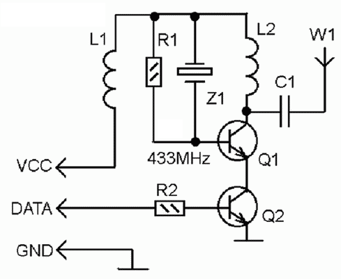 I have not noticed the fundamental advantages of increased nutrition as part of my task. Nevertheless, one should not neglect the fact that there are no special power requirements here, and with increased voltage the device will only work better. It is convenient to connect the transmitter directly to voltage from a 9-12 volt adapter, battery or a set of 6 batteries (Vin Arduino pin). With an unstabilized power supply, which can exceed 12 volts (as, for example, with batteries), I usually decouple the transmitter from the main circuit with a separate 9-volt stabilizer (you can use the simplest 78L09), and I do not see any difference in operation between the 9 and 12 volts. With Uno or Nano, you can use the built-in 5-volt stabilizer to power the controller itself and other circuits (for example, sensors)and for Mini (especially its cheap clones), I would advise you to put a separate 5-volt stabilizer, connecting it to the 5V pin.It should be noted that recently transmitters have appeared that look somewhat non-standard (see. Fig. Below). It turned out that the absence of an L1 throttle (three-turn), from which only holes remained - a fiction, it was simply replaced by the corresponding SMD component. Worse in this option is different: sloppy printing can be misleading regarding the connection of data pins and power. The correct connection is shown in the figure, it is the same for all options:
 The most striking thing in this matter is that when the data and power are mixed up, the transmitter continues to work over short distances! If you look at the circuit, you will understand what it is: the Q2 base through the resistor is connected to the power supply, the transistor is always open, and does not affect the operation of the circuit. A logical high level on the power bus just powers the generator at the right time. The absurdities begin at some distance - it is clear that from a logical conclusion, the power source is bad.
Receiver connection
When purchasing a receiver (it may be called MX-RM-5V or XD-RF-5V), pay attention to the length of the terminals - I somehow came across a whole batch with shortened pins, which caused the receiver to fall out of the standard PBS connector at the slightest distortion and its I had to specifically attach to the board.The receiver circuit is much more complicated (I will not play it, but you can find it, for example, here ). It should receive and amplify a high-frequency signal, filter out the frequency of 433 MHz, isolate bursts and convert them to logical levels. The receiver has a tuning choke (in the middle of the board), but without accurate instruments for measuring the amplitude-frequency characteristics, I do not recommend twisting it - most likely, you will not improve anything, but only spoil it.Since already at a small distance the signal will be much less interference, it is clear that we must deal with interference on all fronts: and circuitry and software methods. Libraries do the last thing for us, but no matter what mathematics are used in software processing, it is advisable to do everything first so that the logical unit at the output appears only when a useful signal bursts and does not appear in the presence of interference. In other words, it would be nice to tune out to the maximum in advance from interference during reception.The standard method of noise reduction, known in my time to every student who has assembled at least one radio or amplifier, is that for nodes that are sensitive to interference, it is necessary to make a separate power supply, isolated to the maximum from other circuits. You can do it in different ways: once you installed a separate zener diode, now they often isolate the power of a problem node with an LC filter (this is recommended, for example, for ADCs, see datasheets for AVR controllers). But in our conditions, when modern components are small and cheap, it is easier to just put a stabilizer separate from the rest on the receiver.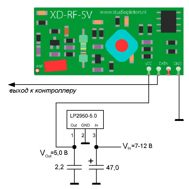 A stabilizer, for example, of type LP2950-5.0 plus two necessary capacitors for it in the cheapest option (when both capacitors are ceramic, in the range of 1-3.3 microfarads) will add sixty maximum to the cost of your circuit. But I prefer not to save: at the output I put an ordinary ceramic, and at the input I put an electrolyte (10–100 μF), moreover, solid-state (polymer) or tantalum. Ceramic capacitors can be dispensed with both there and there, if the input voltage of 7-12 volts comes from battery-batteries or from another analog stabilizer. Pulsed stabilized sources and the simplest unstabilized rectifiers require additional filtering. You can use cheap aluminum electrolyte if you put a ceramic 0.1 microfarad parallel to it,it is even better to put a series inductance at the input of several fractions or units of milligenri.The stabilizer should be installed directly near the receiver, the length of the conductors should be minimal. Instead of the LP2950, you can take the LM2931 or similar with a small pass-through voltage (this is especially important if the circuit is powered by batteries - for a regular LM78L05, the input voltage should be at least 7.5, and preferably 8-9 volts).Comparing with the case of powering the receiver directly from Arduino, as recommended in all publications (I have not seen exceptions), you will be amazed at the effect obtained - the range and ability to penetrate through the walls immediately increases significantly. The receiver, together with the stabilizer, can be carried out in a separate small box for convenience. You can connect its output to the controller in the main body with any three-wire wire (two power supplies and a signal conductor) up to 3 meters long, and maybe more. This is more convenient because antennas are still needed, and according to the rules it will be better if they are parallel to each other in space, and large cases cannot always be placed so that the antennas stick out in the right orientation.In the simplest version, as antennas, you can do with scraps of single-core wire with a cross section of at least 0.5 mm and a length of 17 cm ± 1-3 mm. Do not use stranded mounting wire! More compact spiral antennas are on sale, but I personally have not tested their effectiveness. The antenna tip of both the transmitter and the receiver is sealed into the corresponding hole in the corner of the board (make no mistake in the upgraded version of the transmitter - the word ANT is also out of place there, see fig. Above).
Generation and processing of transmitted data
This is the second major drawback of most reviews on our topic: the authors confine themselves to some local problem, without formulating it in a general way, like transferring arbitrary data in one package. As you understood from the description above, only a simple sequence of bits can be transmitted by our set. The standard VirtualWire library encodes them in a special way (each tetrad is encoded with 6 bits, a synchronization header is added in front, and a checksum for the entire packet is added) and turns the output into a more familiar sequence of bytes. But the programmer already has to deal with it on his own.Further, we assume that the transmitter and receiver are connected to the Arduino. In addition to VirtualWire, in connection with the boom of “smart homes”, there are many other things like RC-Switch or RemoteSwitch, but they are focused on other tasks, and it is clearly not worth using them to transfer arbitrary data.The maximum length of a single message in VirtualWire is 27 bytes (see the documentation ). The transmission of one complete message (it is automatically supplemented with a signature 0xb38, a message length value and a checksum) at my chosen speed of 1200 bps is 0.35 seconds.The more, by the way, the selected transmission speed, the transmission range will be less. From the experience of using RS-232, it is known that with increasing range, the permissible transmission speed exponentially decreases: at a speed of 19,200 an unshielded line runs for 15 meters, at 9600 - 150 meters, and at a speed of 1200 - more than a kilometer. It would be interesting to experimentally find out the nature of this dependence for our case, because a lot here depends on the mathematics used.Initializing the transmitter in VirtualWire looks like this:. . . . .
#include <VirtualWire.h>
. . . . .
void setup() {
vw_setup(1200);
vw_set_tx_pin(10);
. . . . .
}
We will analyze the principles of data generation using a specific example. Let us have a remote temperature-humidity sensor. It gives values (temperature and humidity variables) in the form of a real number with a sign (float). To make it easier to understand at the receiving end, we will all reduce to a positive integer with the number of decimal places at least 4, translate the bits individually into ASCII characters, transfer the resulting string, and perform reverse operations at the receiving end. Of course, you can simplify the task (for example, do without conversion to ASCII and shorten the numbers), but in this form it turns out to be the same for almost any kind of digital data, which simplifies disassembly when receiving.In practice, it is convenient to use the String type to compose a message, something like this:. . . . .
#define ledPin 13
char msg[13];
volatile int tmpr=0;
volatile int hum=0;
. . . . .
void loop() {
delay(1000);
float temperature;
float humidity;
. . . . .
tmpr = temperature*10+2731;
hum = humidity*10+1000;
digitalWrite (ledPin,HIGH);
String strMsg="DAH";
strMsg+=tmpr;
strMsg+=hum;
strMsg.toCharArray(msg,12);
vw_send((uint8_t *)msg, strlen(msg));
vw_wait_tx();
delay(500);
digitalWrite (ledPin, LOW);
}
If you need to transfer more accurate numbers with a large number of digits, then you simply increase the length of the msg array. The global “volatile” variables tmpr and hum are needed if you average several readings, otherwise they can also be declared local inside the loop () function. The message, as you see, consists of converted temperature and humidity values, in ASCII strings of four bytes each, preceded by a string of three “DAH” characters (characters can be any other from the ASCII table). This is a signature that will allow you to distinguish this message from among the possible others sent by similar devices. Do not neglect the signature, even if you believe that other devices nearby in this range are not expected, at the same time it serves as an additional guarantee of the integrity of the received data.Note also that when converting a string to an array, you must specify one character more than the total length of the message (3 + 4 + 4 = 11), this takes into account the zero character that closes the string. And the size of the msg [] array must be specified with a margin and can be any, in this case from 13 to 27 bytes. When transferring, it will still be sent exactly as much as the strlen (msg) function will return, that is, 11 bytes + a null character.In the receiving part, the resulting array of ASCII codes will have to be parsed. But first you need to accept it. To initialize the reception, the following actions are performed:#include <VirtualWire.h>
char str[5]; ASCII
uint8_t buf [VW_MAX_MESSAGE_LEN];
uint8_t buflen = VW_MAX_MESSAGE_LEN;
. . . . .
void setup() {
vw_set_rx_pin(2);
vw_setup(1200);
. . . . .
}
Actually, the technique with parsing a line is this:void loop() {
vw_rx_start();
buflen = VW_MAX_MESSAGE_LEN;
if (vw_have_message()) {
if (vw_get_message(buf, &buflen))
{
vw_rx_stop();
for (byte i=0; i<3; i++)
str[i]= buf[i];
str[3]='\0';
if ((str[0]=='D')&&(str[1]=='A')&&(str[2]=='H')) {
for (byte i=3;i<7;i++)
str[i-3]= buf[i];
int tmpr=atoi(str);
tmpr=tmpr-2731;
. . . . .
. . . . .
for (byte i=7;i<11;i++)
str[i-7]= buf[i];
int hh = atoi(str);
hh=(hh-1000)/10;
if (hh>99) hh=99;
. . . . .
}
}
}
}
I hope you now have fewer questions about using these cheap and easy-to-use devices.