Quick referenceVCV Rack — open source , . VCV
,
.
Ableton Push 2 — midi- Ableton,
DAW,
API .
VCV Rack API
Each module in VCV consists of two parts - audio and graphic. The audio part inherits from the Module class the process method , called for each sample, that is, with a sampling frequency. By the way, the sampling frequency in VCV can vary from standard 44.1 kHz to as much as 768 kHz, which allows more accurately emulating modular synthesizers in the presence of sufficient computing power.Objects of the ModuleWidget type are responsible for the graphics , which inherit the draw method from the base structure . VCV uses the nanovg vector graphics library. Drawing inside the draw methodit can occur both inside the module boundaries (the excess is cut off by the engine), and for example in the framebuffer, which we still use.So what does it take to write your module for VCV?Setting up the environment and installing the Rack SDK
The first step is well described in the documentation and does not cause any difficulties (at least under linux), so we will not dwell on it.Generate a plugin template
There is a helper.py script for this in the Rack SDK. He needs to say createplugin, and then specify the name of the plugin and, optionally, information about it.<Rack SDK folder>/helper.py createplugin MyPlugin
When the plugin template is created, it can be compiled and installed with the commandRACK_DIR=<Rack SDK folder> make install
Draw the frontend of the module
Each plugin can contain several modules, and for each of the modules you need to draw a main panel. For this, VCV documentation offers us to use Inkscape or any other vector editor. Since the modules in VCV are mounted on a virtual Eurorack-stand, their height is always 128.5 mm and the width should be a multiple of 5.08 mm.Basic interface elements, such as CV / Gate sockets, buttons and light bulbs can be marked in vector form. To do this, draw in their place circles of the corresponding colors ( more details here ), so that helper.py then generates code for this markup. Personally, it seemed to me that this is not a very convenient feature and it is easier to place elements directly from the code. When the picture and layout are ready, you need to run helper.py again to create a module template and associate it with the front panel.helper.py createmodule MyModule res/MyModule.svg src/MyModule.cpp
We connect buttons and twists
 Apart from the display, Ableton Push 2 is seen by the computer as a regular USB-MIDI device, which makes it easy to establish a connection between it and VCV Rack. To do this, create an input midi queue and an output midi port inside the class of the module.
Initialization codestruct AbletonPush2 : Module {
midi::Output midiOutput;
midi::InputQueue midiInput;
bool inputConnected;
bool outputConnected;
}
Let's try to find Ableton Push among connected midi devices and connect to it. Since the module is designed to work exclusively with Ableton Push, we do not need to burden the user with a choice of device and you can simply find it by name.Controller Connection Codevoid connectPush() {
auto in_devs = midiInput.getDeviceIds();
for (int i = 0; i < in_devs.size(); i++){
if (midiInput.getDeviceName(in_devs[i]).find("Ableton") != std::string::npos) {
midiInput.setDeviceId(in_devs[i]);
inputConnected = true;
break;
}
}
auto out_devs = midiOutput.getDeviceIds();
for (int i = 0; i < out_devs.size(); i++){
if (midiOutput.getDeviceName(out_devs[i]).find("Ableton") != std::string::npos) {
midiOutput.setDeviceId(out_devs[i]);
outputConnected = true;
break;
}
}
}
Now in the process method you can periodically check whether the controller is connected and ask the midi queue if any messages have arrived. Here it is worth mentioning what and how is generally encoded in the midi standard. In fact, there are two main types of messages, these are Note ON / OFF, transmitting the note number and pressing force, and CC - Command Control, transmitting the numerical value of some variable parameter. More information about midi can be found here .MIDI Queue Polling Codevoid process(const ProcessArgs &args) override {
if (sampleCounter > args.sampleRate / updateFrequency) {
if ((!inputConnected) && (!outputConnected)) {
connectPush();
}
midi::Message msg;
while (midiInput.shift(&msg)) {
processMidi(msg);
}
}
}
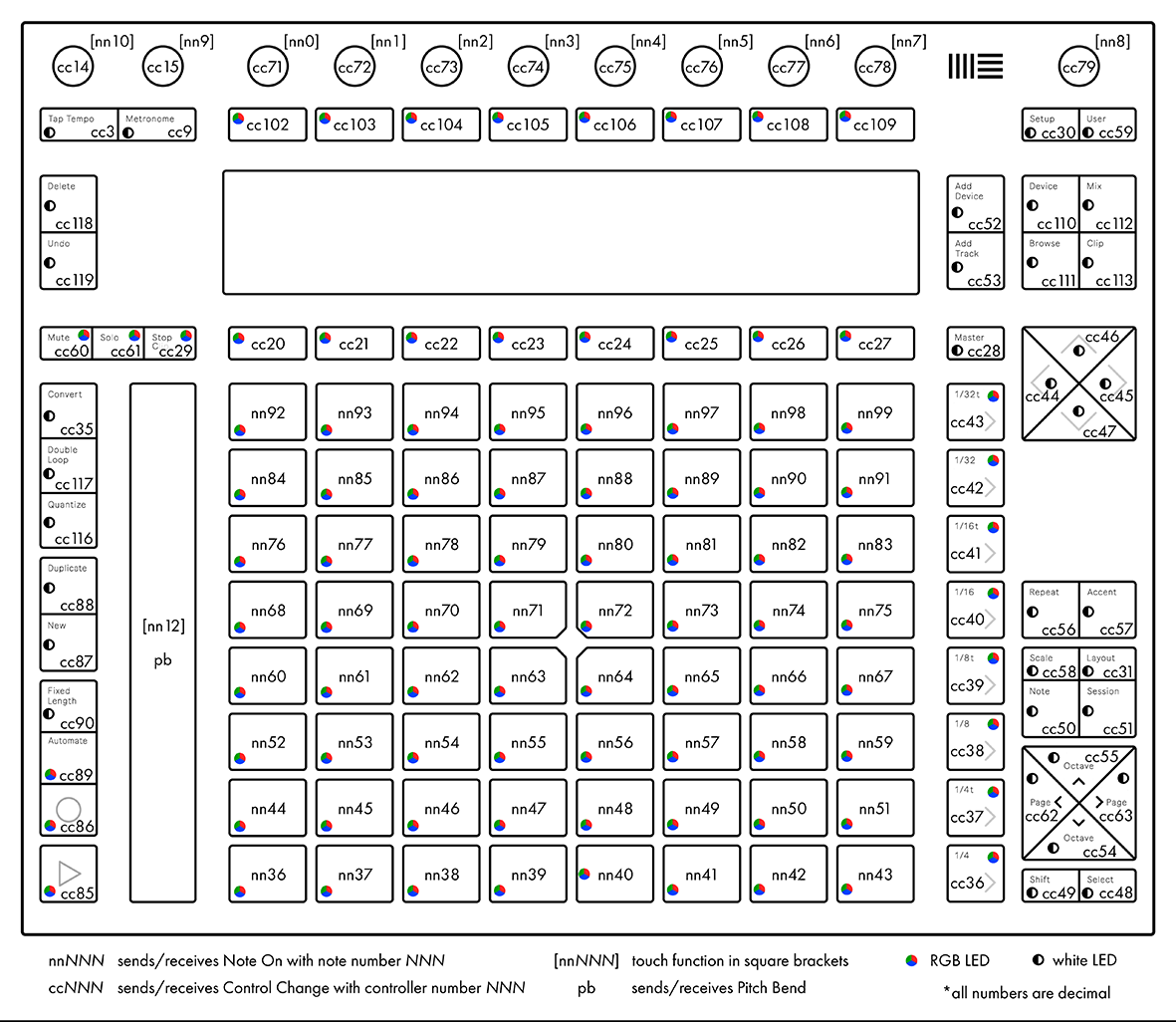
Now I want to teach the controller pads to glow in different colors, so that it is more convenient to navigate them. To do this, we will need to send him the appropriate midi command. Consider, for example, pad number 36 (this is the lowest left pad). If you click on it, the controller will send the command 0x90 (note on), followed by the note number (36) and a number from 0 to 127, which means the strength of the press. And when, on the contrary, the computer sends the same command 0x90 and the same note number 36 to the controller, then the third number will indicate the color with which the lower left pad should glow. The numbers of the buttons and pads are shown in the figure above. Push has quite a few possibilities for working with color, palettes, animation, and other backlighting parameters. I did not go into details and simply brought all the possible colors of the default palette to the pads and chose the ones I liked.But in the general case, the conversion of midi commands to PWM values on LEDs, according to the documentation, looks like this: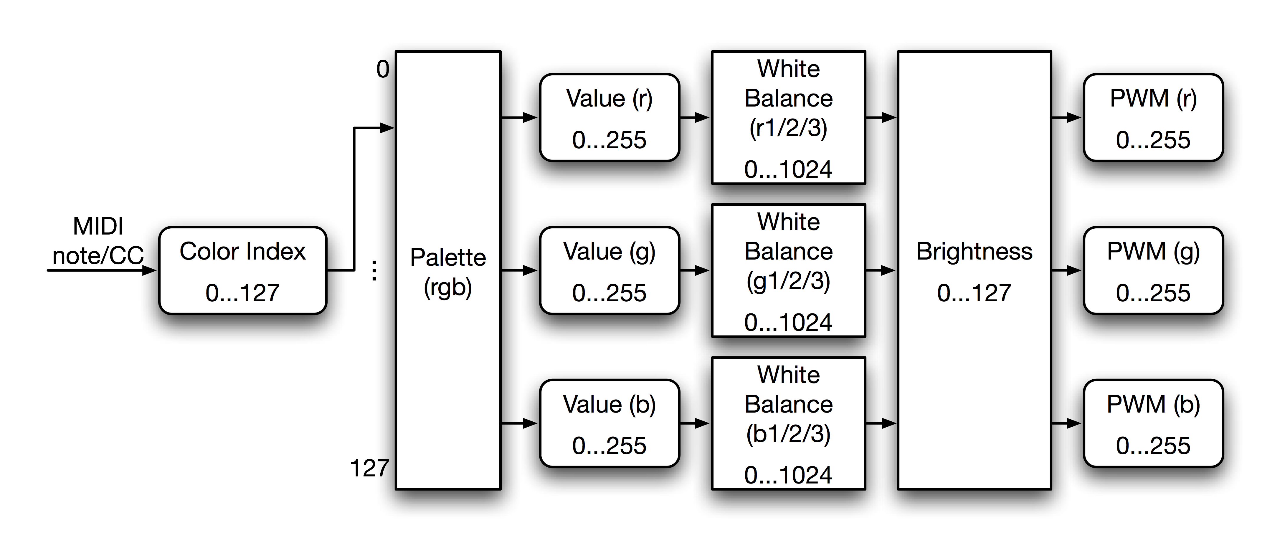
Backlight Control Codevoid lightOn(int note, int color){
midi::Message msg;
msg.setNote(note);
msg.setValue(color);
msg.setChannel(1);
msg.setStatus(0x9);
midiOutput.sendMessage(msg);
}
void lightOff(int note){
midi::Message msg;
msg.setNote(note);
msg.setValue(0);
msg.setChannel(1);
msg.setStatus(0x8);
midiOutput.sendMessage(msg);
}
We connect the display
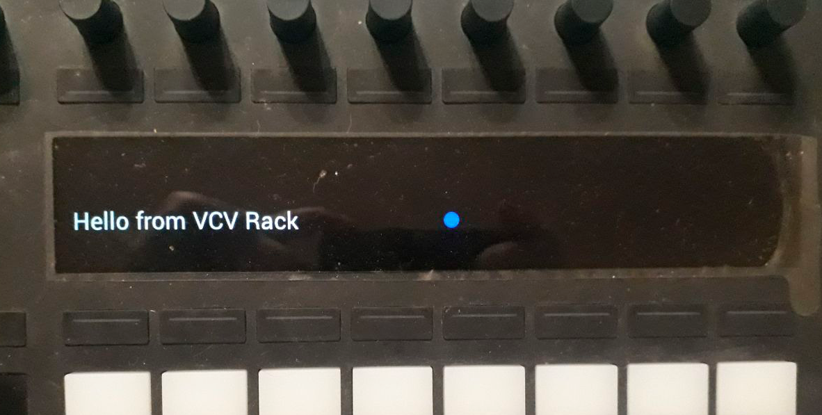 To connect the display you have to work with USB. The controller itself does not know how to draw anything and does not know anything about graphics. All he wants is to send a frame of 160x960 pixels in size at least every 2 seconds. All rendering takes place on the side of the computer. To start, connect and open the USB device, as described in the documentation :
Display Connection Code#ifdef _MSC_VER
#define _CRT_SECURE_NO_WARNINGS
#endif
#include <stdio.h>
#ifdef _WIN32
#pragma warning(disable:4200)
#include <windows.h>
#endif
#ifdef __linux__
#include <libusb-1.0/libusb.h>
#else
#include "libusb.h"
#endif
#define ABLETON_VENDOR_ID 0x2982
#define PUSH2_PRODUCT_ID 0x1967
static libusb_device_handle* open_push2_device()
{
int result;
if ((result = libusb_init(NULL)) < 0)
{
printf("error: [%d] could not initilialize usblib\n", result);
return NULL;
}
libusb_set_debug(NULL, LIBUSB_LOG_LEVEL_ERROR);
libusb_device** devices;
ssize_t count;
count = libusb_get_device_list(NULL, &devices);
if (count < 0)
{
printf("error: [%ld] could not get usb device list\n", count);
return NULL;
}
libusb_device* device;
libusb_device_handle* device_handle = NULL;
char ErrorMsg[128];
sprintf(ErrorMsg, "error: Ableton Push 2 device not found\n");
for (int i = 0; (device = devices[i]) != NULL; i++)
{
struct libusb_device_descriptor descriptor;
if ((result = libusb_get_device_descriptor(device, &descriptor)) < 0)
{
sprintf(ErrorMsg,
"error: [%d] could not get usb device descriptor\n", result);
continue;
}
if (descriptor.bDeviceClass == LIBUSB_CLASS_PER_INTERFACE
&& descriptor.idVendor == ABLETON_VENDOR_ID
&& descriptor.idProduct == PUSH2_PRODUCT_ID)
{
if ((result = libusb_open(device, &device_handle)) < 0)
{
sprintf(ErrorMsg,
"error: [%d] could not open Ableton Push 2 device\n", result);
}
else if ((result = libusb_claim_interface(device_handle, 0)) < 0)
{
sprintf(ErrorMsg,
"error: [%d] could not claim interface 0 of Push 2 device\n", result);
libusb_close(device_handle);
device_handle = NULL;
}
else
{
break;
}
}
}
if (device_handle == NULL)
{
printf(ErrorMsg);
}
libusb_free_device_list(devices, 1);
return device_handle;
}
static void close_push2_device(libusb_device_handle* device_handle)
{
libusb_release_interface(device_handle, 0);
libusb_close(device_handle);
}
To transmit a frame, you must first send a 16-byte header, and then 160 lines of 960 16-bit numbers each. At the same time, according to the documentation, strings should not be transmitted in 1920 bytes, but in packets of 2048 bytes, supplemented with zeros.Frame Transfer Codestruct Push2Display : FramebufferWidget {
unsigned char frame_header[16] = {
0xFF, 0xCC, 0xAA, 0x88,
0x00, 0x00, 0x00, 0x00,
0x00, 0x00, 0x00, 0x00,
0x00, 0x00, 0x00, 0x00
};
libusb_device_handle* device_handle;
unsigned char* image;
void sendDisplay(unsigned char * image) {
int actual_length;
libusb_bulk_transfer(device_handle, PUSH2_BULK_EP_OUT, frame_header, sizeof(frame_header), &actual_length, TRANSFER_TIMEOUT);
for (int i = 0; i < 160; i++)
libusb_bulk_transfer(device_handle, PUSH2_BULK_EP_OUT, &image[(159 - i)*1920], 2048, &actual_length, TRANSFER_TIMEOUT);
}
}
Now it remains only to draw and write a frame to the buffer. To do this, use the FramebufferWidget class that implements the drawFramebuffer method . VCV Rack out of the box uses the nanovg library , so it's pretty easy to write graphics here. We learn the current graphic context from the global variable APP and save its state. Next, create an empty 160x960 frame and draw it with the draw method . After that, copy the framebuffer to the array that will be sent via USB, and return the state of the context. At the end, set the dirty flag so that at the next iteration of the rendering, the VCV engine does not forget to update our widget.Frame Rendering Codevoid drawFramebuffer() override {
NVGcontext* vg = APP->window->vg;
if (display_connected) {
nvgSave(vg);
glViewport(0, 0, 960, 160);
glClearColor(0, 0, 0, 0);
glClear(GL_COLOR_BUFFER_BIT|GL_STENCIL_BUFFER_BIT);
nvgBeginFrame(vg, 960, 160, 1);
draw(vg);
nvgEndFrame(vg);
glReadPixels(0, 0, 960, 160, GL_RGB, GL_UNSIGNED_SHORT_5_6_5, image);
for (int i = 0; i < 80*960; i ++){
image[i * 4] ^= 0xE7;
image[i * 4 + 1] ^= 0xF3;
image[i * 4 + 2] ^= 0xE7;
image[i * 4 + 3] ^= 0xFF;
}
sendDisplay(image);
nvgRestore(vg);
}
dirty = true;
}
Logic of interaction and mapping of parameters
For my task, I wanted to be able to switch patterns recorded in sequencers, and at the same time control a certain set of parameters, my own for each group of patterns. By mapping, I understand the binding of the parameter of one module with the parameter of another module or midi controller. I found very little information on how to make mapping beautifully, so I took most of the code that implements it from the MIDI Map module built into VCV . In short, for each bunch of parameters a special ParamHandle object is created there , which tells the engine through crutches what is connected with what.Conclusion
Here is a module I got in the end. In addition to the standard conversion of midi to CV, it allows you to group pads, assign colors to them, and associate arbitrary module parameters with Push encoders, displaying their names and values on the controller display. In the video below you can see his overview, and in this video you can see in action.The full code is available here .We managed to test it only under Linux (Ubuntu 18.04), on MacOS the display did not connect due to the specifics of libusb and there were strange delays in the midi interface. Despite this, VCV Rack left a very good impression both as a framework and as a modular DAW, I hope that VCV will continue to develop, and this article will help someone else write their own modules for it.