Hello everyone.We, Victor Antipov and Ilya Aleshin, today will talk about our experience with USB devices through Python PyUSB and a little about reverse engineering.
Background
In 2019, Decree of the Government of the Russian Federation No. 224 “On approval of the rules for labeling tobacco products by means of identification and the specifics of introducing a state information system for monitoring the circulation of goods subject to mandatory labeling by means of identification in relation to tobacco products” entered into force.The document explains that from July 1, 2019, manufacturers are required to label each pack of tobacco. And direct distributors should receive these products with the design of a universal transfer document (UPD). Shops, in turn, need to register the sale of labeled products through the cash register.Also, from July 1, 2020, unmarked tobacco products are banned. This means that all packs of cigarettes must be labeled with a special Datamatrix barcode. And - an important point - it turned out that Datamatrix will not be ordinary, but inverse. That is, not a black code on white, but vice versa.We tested our scanners, and it turned out that most of them need to be reflashed / retrained, otherwise they simply are not able to work normally with this barcode. This turn of events guaranteed us a severe headache, because our company has a lot of stores that are scattered across a vast territory. Several tens of thousands of cash desks - and extremely little time.What was to be done? There are two options. First: engineers at the facility manually reflash and adjust the scanners. Second: we work remotely and, preferably, we cover many scanners at once in one iteration.The first option, obviously, did not suit us: we would have to spend money on field trips of engineers, and in this case it is difficult to control and coordinate the process. But the most important thing is that people would work, that is, potentially we would get a lot of mistakes and, most likely, would not fit the deadline.The second option is good for everyone, if not for one but. Some vendors did not have the remote flashing tools we needed for all the required operating systems. And since the deadlines were running out, I had to think with my own head.Next, we will describe how we developed tools for handheld scanners for the Debian 9.x OS (we have all the Debian box office).:
Says Victor Antipov.The official utility provided by the vendor works under Windows, and only with IE. The utility can flash and configure the scanner.Since the target system is Debian, we installed the usb-redirector server on the Debian server and the usb-redirector client on the Windows. Using the usb-redirector utilities, the scanner was forwarded from the Linux machine to the Windows machine.The utility from the Windows vendor saw the scanner and even flashed it normally. Thus, the first conclusion was made: nothing depends on the OS, the matter is in the flashing protocol.OK. A flashing was launched on a Windows machine, and a dump was removed on a Linux machine.They stuffed the dump into WireShark and ... were sad (I’ll omit part of the dump details, they are of no interest).What dump showed us: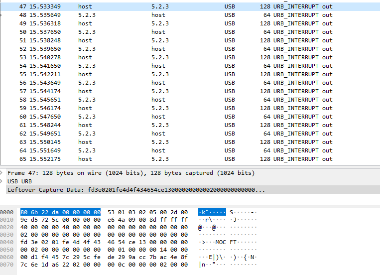
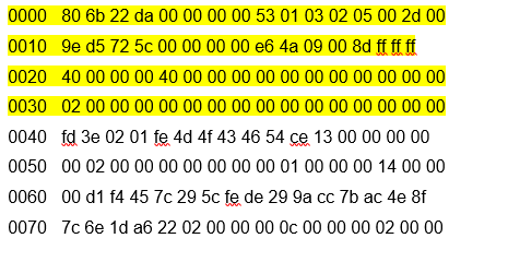 The addresses 0000-0030, judging by Wireshark, are USB service information.We were interested in part 0040-0070.Nothing was clear from one transmission frame, except for MOCFT characters. These symbols turned out to be symbols from the firmware file, as well as the rest of the symbols until the end of the frame (the firmware file is highlighted):
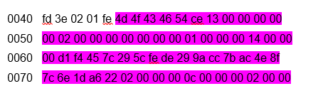 What did the symbols fd 3e 02 01 fe mean, I personally, like Ilya, had no idea.I looked at the next frame (service information is deleted here, the firmware file is highlighted):
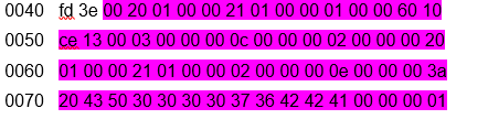 What became clear? That the first two bytes are some kind of constant. All subsequent blocks confirmed this, but before the end of the transmission block:
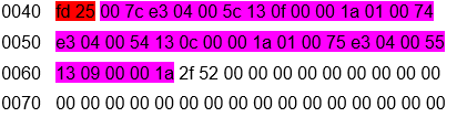 This frame also entered into a stupor, since the constant changed (highlighted) and, strangely enough, there was a part of the file. The size of the transmitted bytes of the file indicated that 1024 bytes were transferred. What the remaining bytes meant - I did not know again.First of all, like an old BBS nickname, I revised the standard transfer protocols. 1024 bytes, no protocol passed. He began to study the materiel and stumbled upon the 1K Xmodem protocol. It allowed to transmit 1024, but with a nuance: at first only 128, and only in the absence of errors did the protocol increase the number of bytes transmitted. I immediately had a transmission of 1024 bytes. I decided to study the transmission protocols, and specifically the X-modem.There were two variations of the modem.First, the format of the XMODEM package with CRC8 support (original XMODEM):
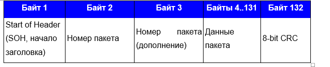 Secondly, the XMODEM packet format with CRC16 support (XmodemCRC):
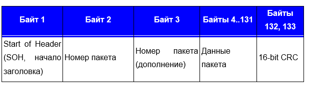 It looks similar, with the exception of SOH, packet number and CRC and the length of the packet.I looked at the beginning of the second transmission block (and again saw the firmware file, but with an indent of 1024 bytes):
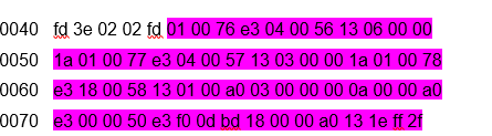 I saw the familiar header fd 3e 02, but the next two bytes have already changed: it was 01 fe, and it became 02 fd. Then I noticed that the second block is now numbered 02 and thus understood: in front of me is the numbering of the transmission block. The first 1024 transmission is 01, the second 02, the third 03 and so on (but in hex, of course). But what does the change from fe to fd mean? The eyes saw a decrease of 1, the brain reminded that programmers count from 0, not from 1. But then why is the first block 1, not 0? I did not find the answer to this question. But I understood how the second block is considered. The second block is nothing more than FF - (minus) the number of the first block. Thus, the second block was designated as = 02 (FF-02) = 02 FD. Subsequent reading of the dump confirmed my hunch.Then the following picture of the program began to emerge:The beginning of the programfd 3e 02 - Start01 FE - transmission counterTransmission (34 blocks, 1024 bytes are transmitted)fd 3e 1024 bytes of data (divided into blocks of 30 bytes).End of transmissionfd 25Remains of data to align to 1024 bytes.What does the block transfer end frame look like:
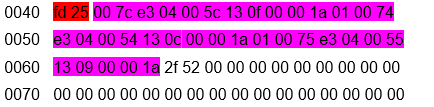 fd 25 - signal to the end of the block transfer. Next 2f 52 - the remains of the file up to 1024 bytes. 2f 52, judging by the protocol, is a 16-bit CRC checksum.Based on old memory, I made a program in C that pulled 1024 bytes from a file and read 16-bit CRC. The launch of the program showed that this is not a 16-bit CRC. Again stupor - for about three days. All this time I tried to understand what it could be if not a checksum. Studying English-language sites, I found that the X-modem uses its own checksum calculation - CRC-CCITT (XModem). I did not find any implementations in C for this calculation, but I found a site that read this checksum online. By uploading 1024 bytes of my file to the web page, the site showed me a checksum that completely coincided with the checksum from the file.Hooray! The last riddle is solved, now you had to make your own firmware. Then I transferred my knowledge (and they remained only in my head) to Ilya, who is familiar with powerful tools - Python.
Program creation
Narrated by Ilya Aleshin.Having received the appropriate instructions, I was very “happy”.Where to begin? Right, from the beginning. From dumping from a USB port.Run USB-pcap https://desowin.org/usbpcap/tour.htmlSelect the port to which the device is connected and the file where we will save the dump.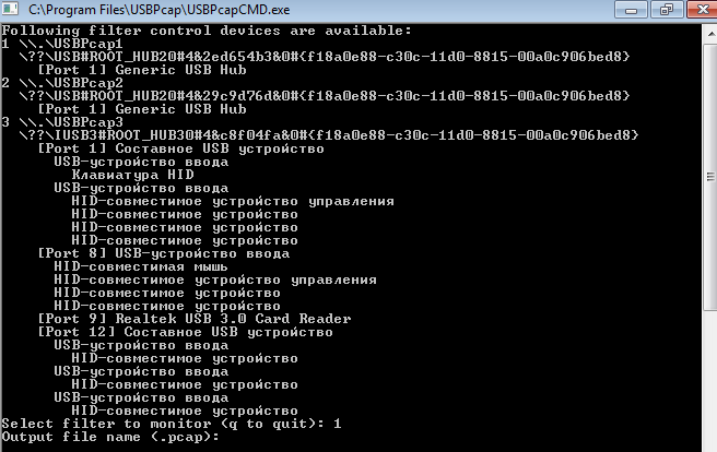 We connect the scanner to the machine where the native EZConfigScanning software for Windows is installed.
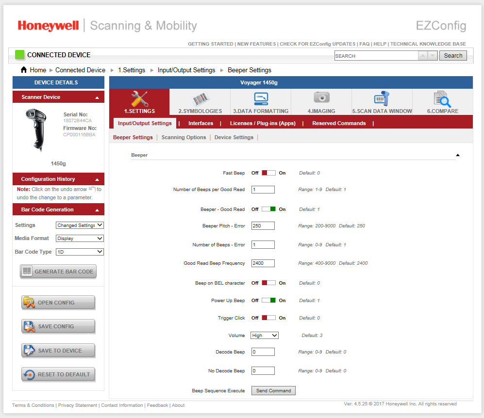 In it we find the point of sending commands to the device. But what about the teams? Where to get them?When the program starts, the equipment is interrogated automatically (we will see this a bit later). And there were training barcodes from official equipment documents. DEFALT. This is our team.
 The necessary data is received. Open dump.pcap through wireshark.Block at startup EZConfigScanning. The red points are places to pay attention to.
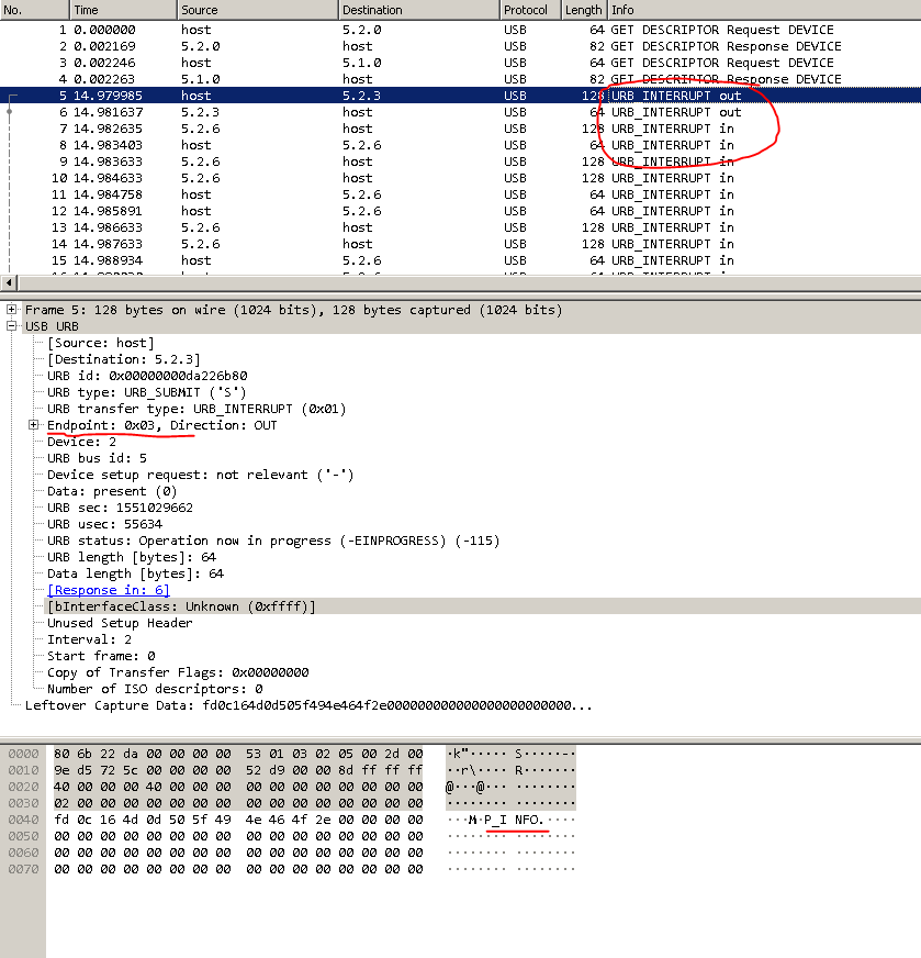
 Seeing all this for the first time, I lost heart. Where to dig further is unclear.A bit of a brainstorming and-and-and ... Aha! In a dump, out is in , and in is out .Googled what URB_INTERRUPT is. Found out that this is a data transfer method. And there are 4 such methods: control, interrupt, isochronous, bulk. You can read about them separately.And the endpoint addresses in the USB device interface can be obtained either through the “lsusb –v” command, or by means of pyusb.Now you need to find all the devices with this VID. You can search specifically by VID: PID.
 It looks like this:
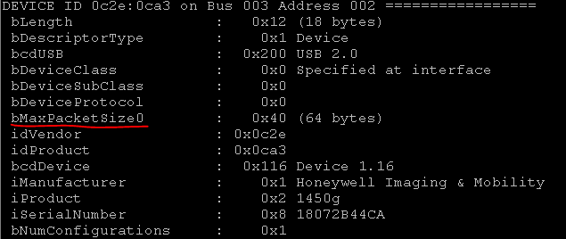
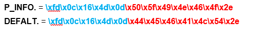
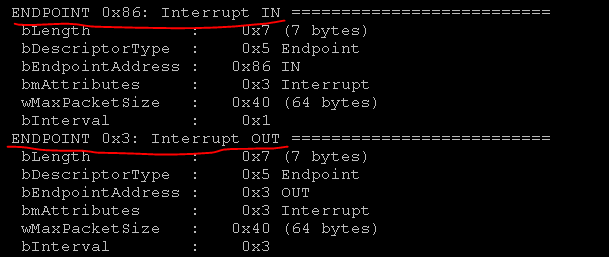 So, we have the necessary information: P_INFO commands. or DEFALT, addresses where to write the commands endpoint = 03 and where to get the answer endpoint = 86. It remains only to translate the commands in hex.
 Since we already found the device, disconnect it from the kernel ...
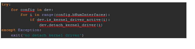 ... and write to endpoint with address 0x03,
 ... and then read the response from endpoint with address 0x86.
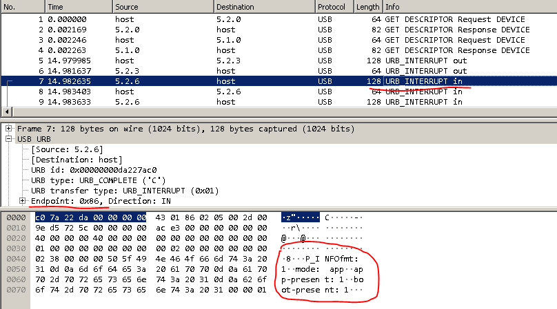
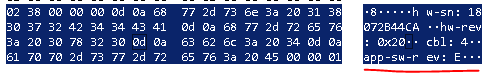
 Structured answer:
P_INFOfmt: 1
mode: app
app-present: 1
boot-present: 1
hw-sn: 18072B44CA
hw-rev: 0x20
cbl: 4
app-sw-rev: CP000116BBA
boot-sw-rev: CP000014BAD
flash: 3
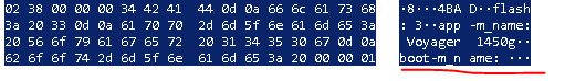
app-m_name: Voyager 1450g
boot-m_name: Voyager 1450g
app-p_name: 1450g
boot-p_name: 1450g
boot-time: 16:56:02
boot-date: Oct 16 2014
app-time: 08:49:30
app-date: Mar 25 2019
app-compat: 289
boot-compat: 288
csum: 0x6986
We see this data in dump.pcap.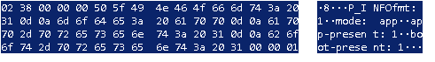
 Fine! We translate system barcodes to hex. Everything, the training functionality is ready.What to do with firmware? It seems that everything is the same, but there is a nuance.Having removed a complete dump of the flashing process, we roughly understood what we were dealing with. Here is an article about XMODEM that really helped to understand how this communication happens, albeit in general terms: http://microsin.net/adminstuff/others/xmodem-protocol-overview.html I recommend reading it.Looking in the dump, you can see that the frame size is 1024, and the size of URB-data is 64.
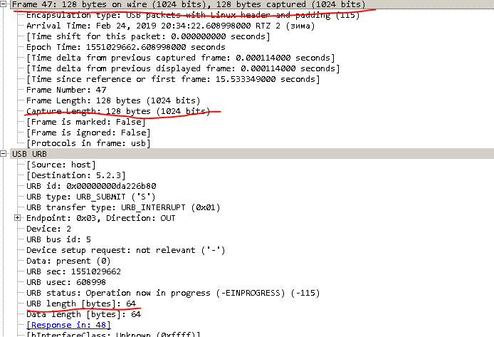 Therefore, 1024/64, we get 16 lines in a block, read the firmware file by 1 character and form a block. Supplementing 1 line in a block with special characters fd3e02 + block number.The next 14 lines are supplemented with fd25 +, using XMODEM.calc_crc () we calculate the checksum of the entire block (it took a lot of time to understand that “FF - 1” is CSUM) and the last 16th line is supplemented with fd3e.It would seem that everything, read the firmware file, hit the blocks, disconnect the scanner from the kernel and send it to the device. But not so simple. The scanner must be put into firmware mode bysending it NEWAPP = '\\ xfd \\ x0a \\ x16 \\ x4e \\ x2c \\ x4e \\ x45 \\ x57 \\ x41 \\ x50 \\ x50 \\ x0d'.Where does this command come from ?? From the dump.
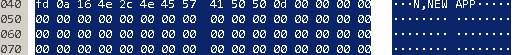 But we cannot send the whole block to the scanner due to the restriction of 64:
 Well, the scanner in the NEWAPP flashing mode does not accept hex either. Therefore it is necessary to translate each line bytes_array
[253, 10, 22, 78, 44, 78, 69, 87, 65, 80, 80, 13, 0, 0, 0, 0, 0, 0, 0, 0, 0, 0, 0, 0, 0, 0, 0, 0, 0, 0, 0, 0, 0, 0, 0, 0, 0, 0, 0, 0, 0, 0, 0, 0, 0, 0, 0, 0, 0, 0, 0, 0, 0, 0, 0, 0, 0, 0, 0, 0, 0, 0, 0, 0]
And already send this data to the scanner.We get the answer:[2, 1, 0, 0, 0, 6, 0, 0, 0, 0, 0, 0, 0, 0, 0, 0, 0, 0, 0, 0, 0, 0, 0, 0, 0, 0, 0, 0, 0, 0, 0, 0, 0, 0, 0, 0, 0, 0, 0, 0, 0, 0, 0, 0, 0, 0, 0, 0, 0, 0, 0, 0, 0, 0, 0, 0, 0, 0, 0, 0, 0, 0, 0, 0]
If you check the article about XMODEM, it becomes clear: the data has been accepted.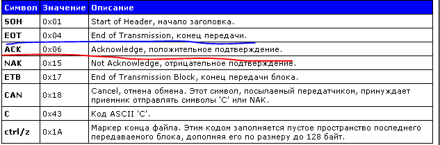 After all the blocks have been transferred, we complete the transfer END_TRANSFER = '\ xfd \ x01 \ x04'.Well, since these blocks do not carry any information for ordinary people, we’ll make the firmware in hidden mode by default. And just in case, through tqdm we will organize a progress bar.
 Actually, the rest is small. It remains only to wrap the solution in scripts for mass replication at a clearly defined time, so as not to slow down the process of working at the box office, and add logging.
Total
Having spent a lot of time and energy and hair on the head , we were able to develop the solutions we needed, moreover, we met the deadline. At the same time, scanners are reflashed and retrained now centrally, we clearly control the entire process. The company saved time and money, and we gained invaluable experience in reverse engineering of this type of equipment.