How it all began
I welcome everyone. I’m Maxim and I want to share information about how I assembled a radio-controlled submarine without any knowledge of electronics at the beginning of my journey. I myself am an animation and computer graphics artist - I have never done programming or electronics. I had only a small supply of knowledge about soldering, which my grandfather gave me when I was still a primary school student.All my life I was interested in the topic of underwater research, it all began at the same time, in childhood, with J.I. Cousteau, and ended with the development of a game about the icy oceans of Europe. But, however, now is not about that.Having decided that it was time to transfer my hobbies to the plane of practice - I went to Youtube. I got a handful of the most basic knowledge and then my path lay already on AliExpress, like many. It all ended up with the purchase of 27 names of various modules and other components.
 The post office employee was very unhappy when looking for 27 parcels ...
The beginning of work on the submarine and the first failures
At first I found a man who knows firsthand about submarines; he helped me with theory and tests.Next, I immediately started writing my first code for Arduino. It was a code for controlling two submarine engines. Two potentiometers: the left controls the total power of the engines, and the right controls the rotation of the submarine (reduces the power of one of the engines, depending on the position of the potentiometer). All this I displayed on an inexpensive display, as I planned to make a separate control panel (as a result, the submarine is controlled via a smartphone). Considering that a week ago I did not know how potentiometers work, my enthusiasm was indescribable. Not stopping there, I went to a hardware store and a pharmacy. In the construction industry, I scored various polypropylene pipes, couplings and clamps, and in the pharmacy I took several Janet syringes.Pipes, respectively, went to the hull of the submarine, and syringes to the module change buoyancy. Just the module for changing buoyancy turned out to be the most problematic part for me.
Buoyancy Modulus
The tasks of this module are quite simple, collect water and squeeze it back on command. And the question arose - how to push the piston of a syringe, having a handful of servos, motors and a set of gears? It’s not worth pushing like that: It was the first experience of interacting with gears and other trifles. By the way, I was able to remake the sg90 servo for 360 ° rotation: I sharpened the latch on the main gear, which turned the potentiometer, and glued the potentiometer shaft in the zero position, so that it would not accidentally rotate even with a trimmed limiter.This still did not help to solve the problem - I could not reliably fix the gear interacting with the gear rack. The gained engineering experience helped me to master the buoyancy change module the second time: I took a more powerful servo, a thick threaded rod and a nut that I fixed on the piston. This time I did not bother with the modification of the servo, I decided that it is easier to use an external driver and connect directly to the servo motor.
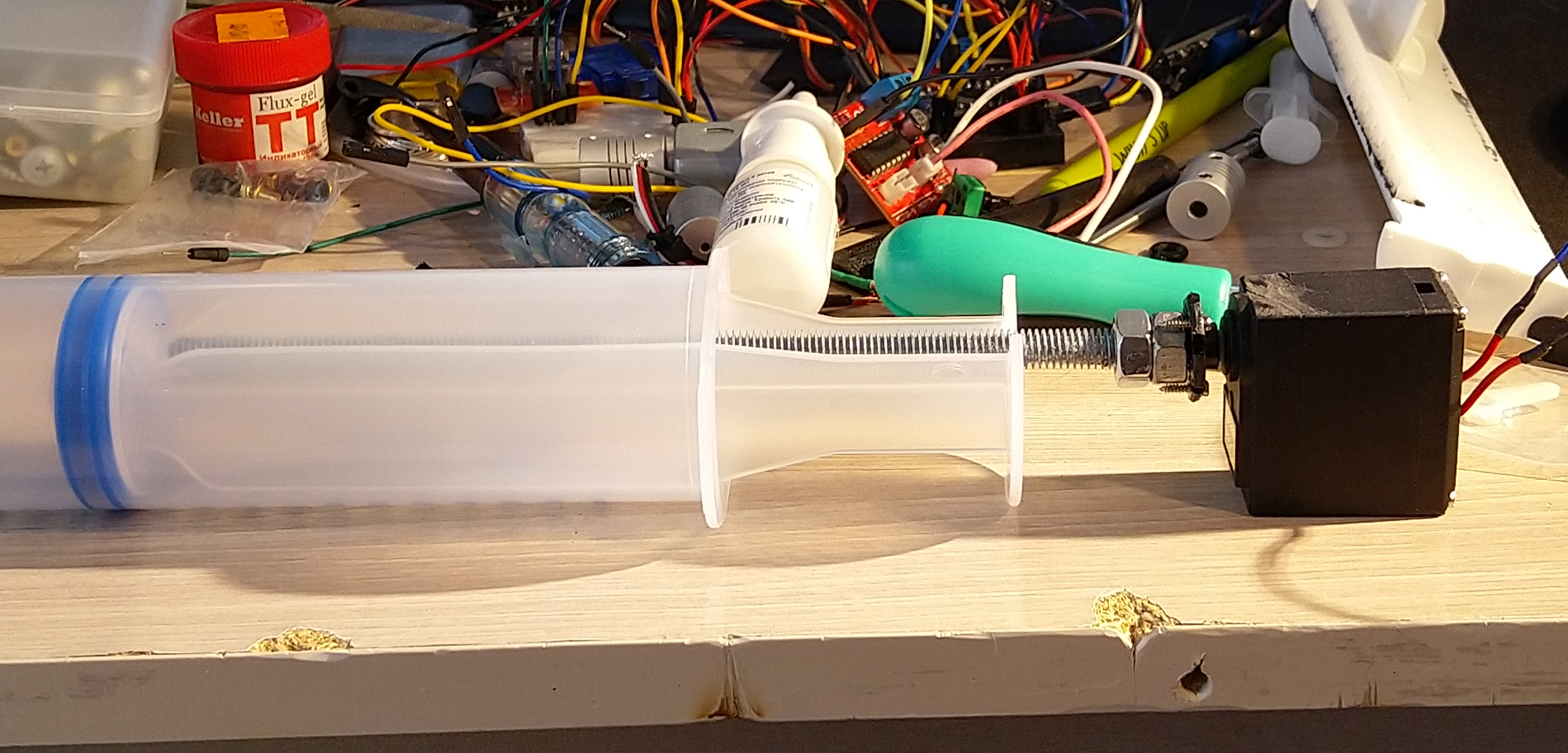
Wasyansky flexible coupling Aluminum frame for stiffness A laser rangefinder was placed on the piston so that I could determine in real time - in what position it is now. Well, based on this distance data, I prescribed a piston lock when it is in extreme positions. Perhaps there are simpler methods for determining the position of the piston, but I accidentally found a very cheap module from the Chinese - the VL53L0X range finder and decided to use it. As a result, I was very pleased, the library is simple, it works as it should, I advise. The accuracy in the confined space of the syringe is somewhere around 5mm, in principle, that was enough for me.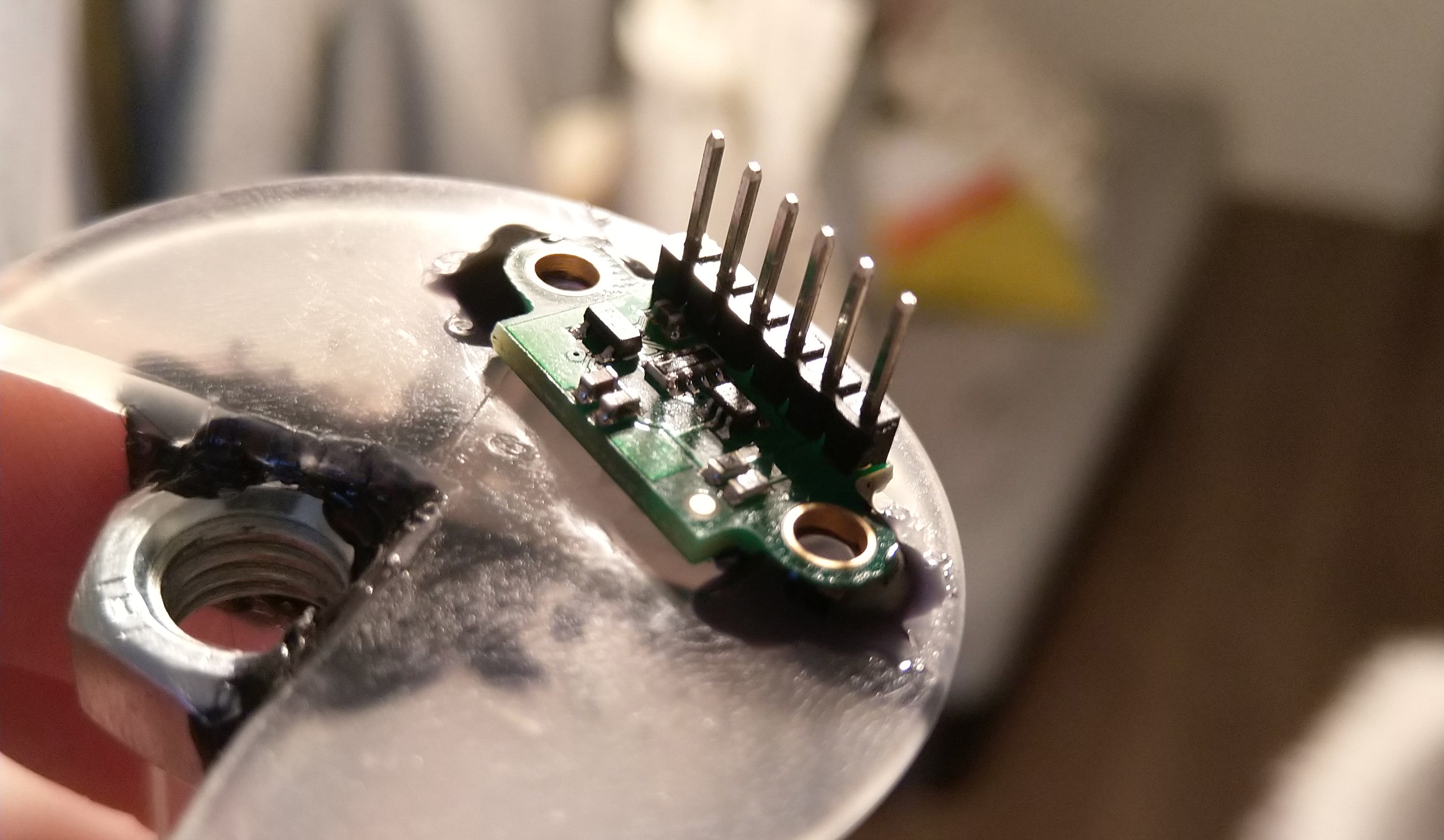 During testing, another problem arose - the piston adheres strongly to the walls of the syringe. I don’t know what it’s connected with, but to start the movement of the piston it is necessary to apply considerable force, after the initial jam it goes on normally. We tried almost all types of lubricants - many of them made it worse. For this reason, I had to add an aluminum frame for the module.
Motors
With the propulsion system, I settled on the simplest solution and took ready-made underwater motors. Prior to this, I tested the option with a motor inside the case. I ordered a stern tube in a set with a shaft and screws, but as I studied the issue, it turned out that for my purposes I needed a whole system: a complex oil seal, flanges, etc. Otherwise, it will proceed in any case. I have plans for the future to throw the submarine somewhere on Ladoga and manage it via 3G networks, sitting at home on the couch, which means that any possible leaks will lead to a small autonomy of the device.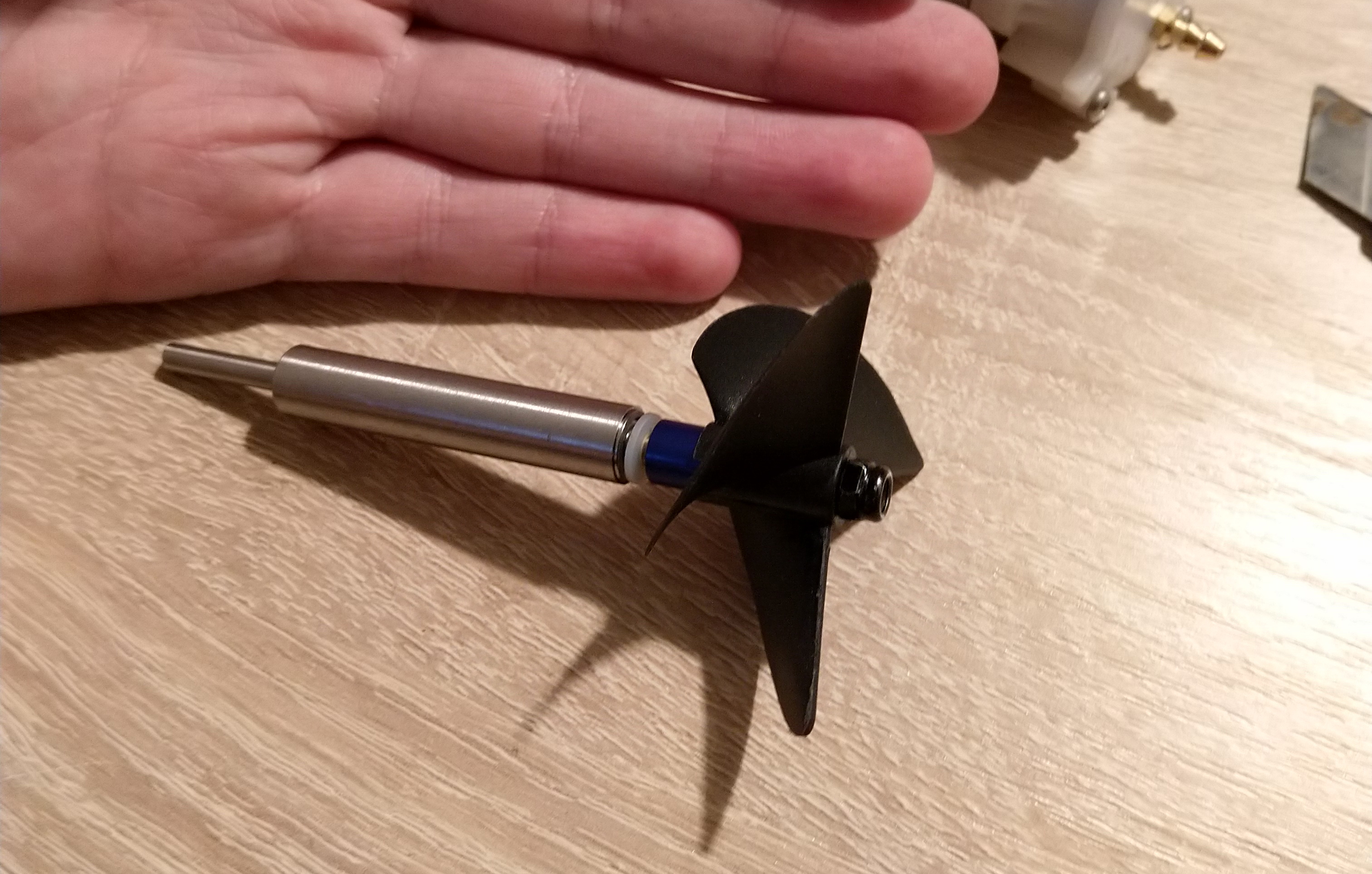 In the future I plan to use only underwater motors, most likely brushless. At the moment, these are used, collector:
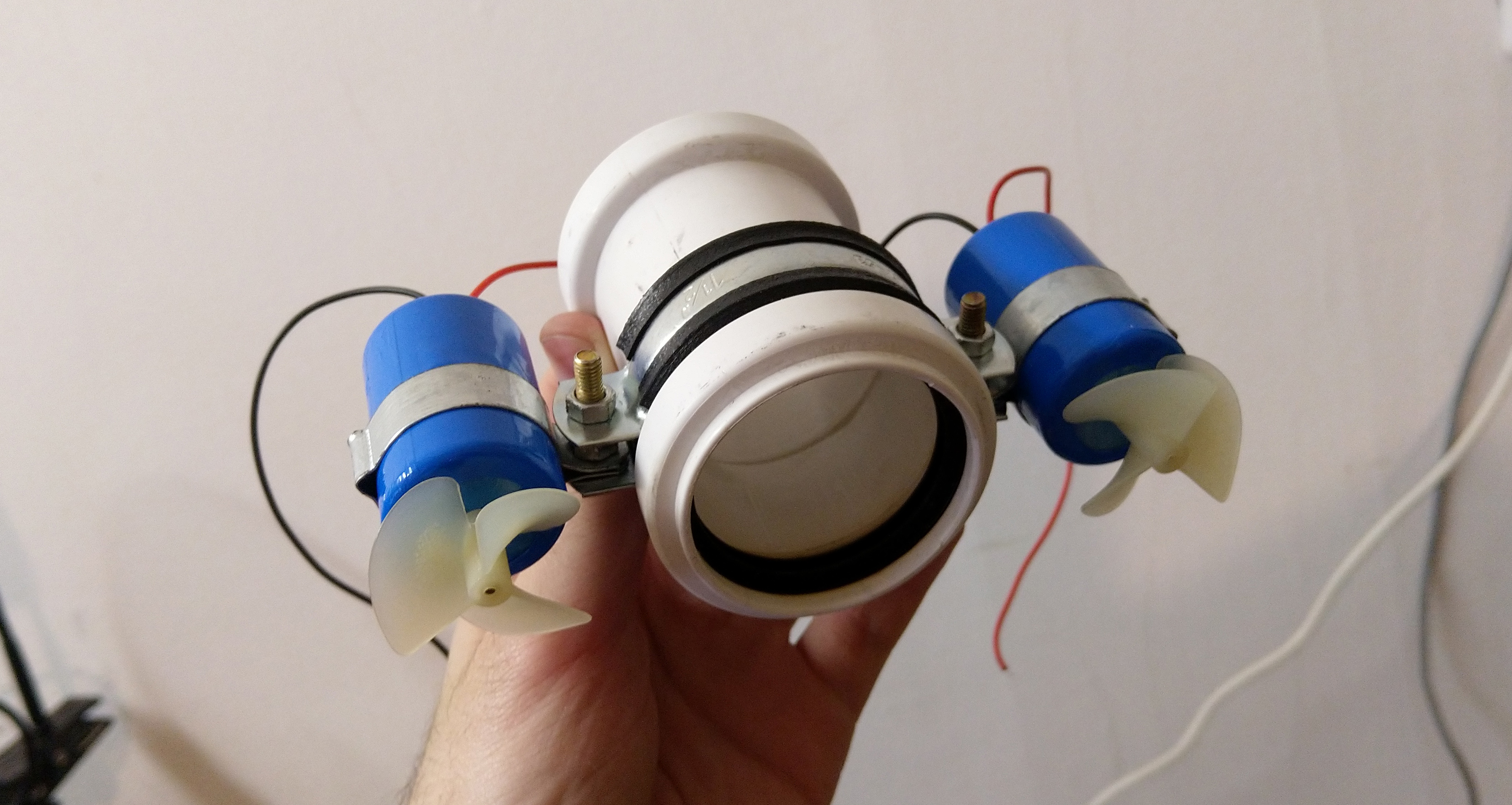 I control them using PWM. The seller says that they are maximum 8 meters deep, which, again, imposes some restrictions immediately.
Housing
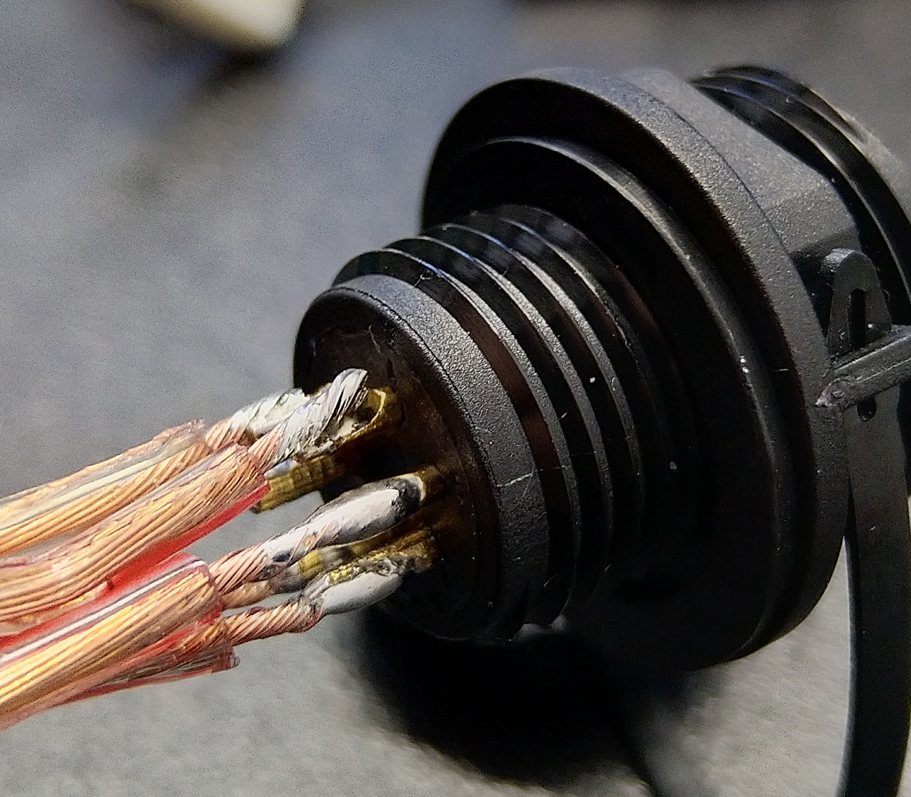
The case was an interesting task - to make a sealed connection, which would be easily disassembled. I did not fulfill the task, I had to glue everything tightly. When the syringe draws water, pressure is created inside the body and all of our fasteners simply squeezed out. As a result, all the important wires were brought to a sealed connector, through which you can charge the device, and flash the onboard Arduino, and connect the antenna.Yes, our antenna is connected using a cable and is in the surface position, guaranteeing reliable communication. But about the antenna a bit later.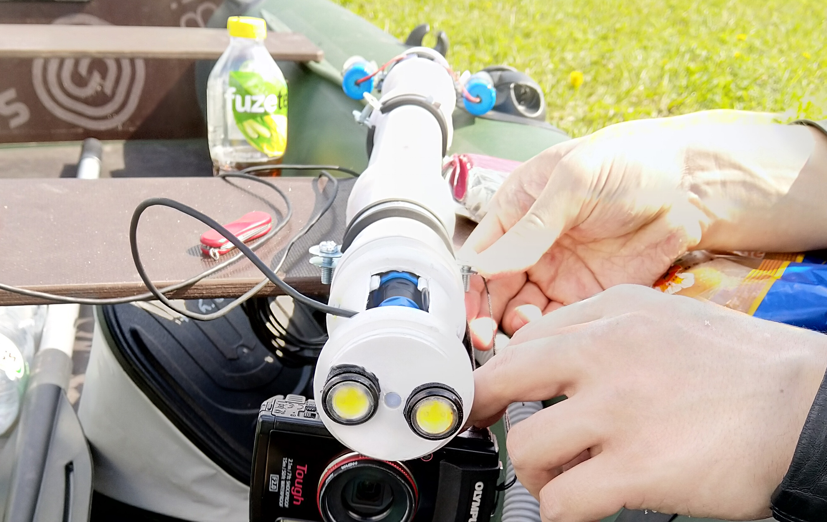 The housing consists of 50mm polypropylene pipes and couplings. The joints are covered with sealed paste, and on top, for strength, filled with hot melt. A syringe nozzle, an airtight connector, an inclusion toggle switch and two wires for searchlights were brought to the end. Floodlights mounted on the bow of the flooded part, this design allowed to shift the center of gravity closer to the center of the submarine.
Submarine Brains
This is the most interesting part for me. When I started to work out the circuit, I still did not know how, for example, capacitors work and why they are needed. I was very happy when, when turning off the power, the LED on the Arduino slowly faded due to a capacitive capacitor.In fact, they were useful in the circuit for smoothing the peaks arising in the circuit due to the operation of the collector motors. They are also needed to connect a voltage regulator.We have a battery of two cells, respectively 8.4 V, the voltage goes to the motors, and 5 V after the stabilizer - to the Arduino and other sensors. Full-size scheme (clickable):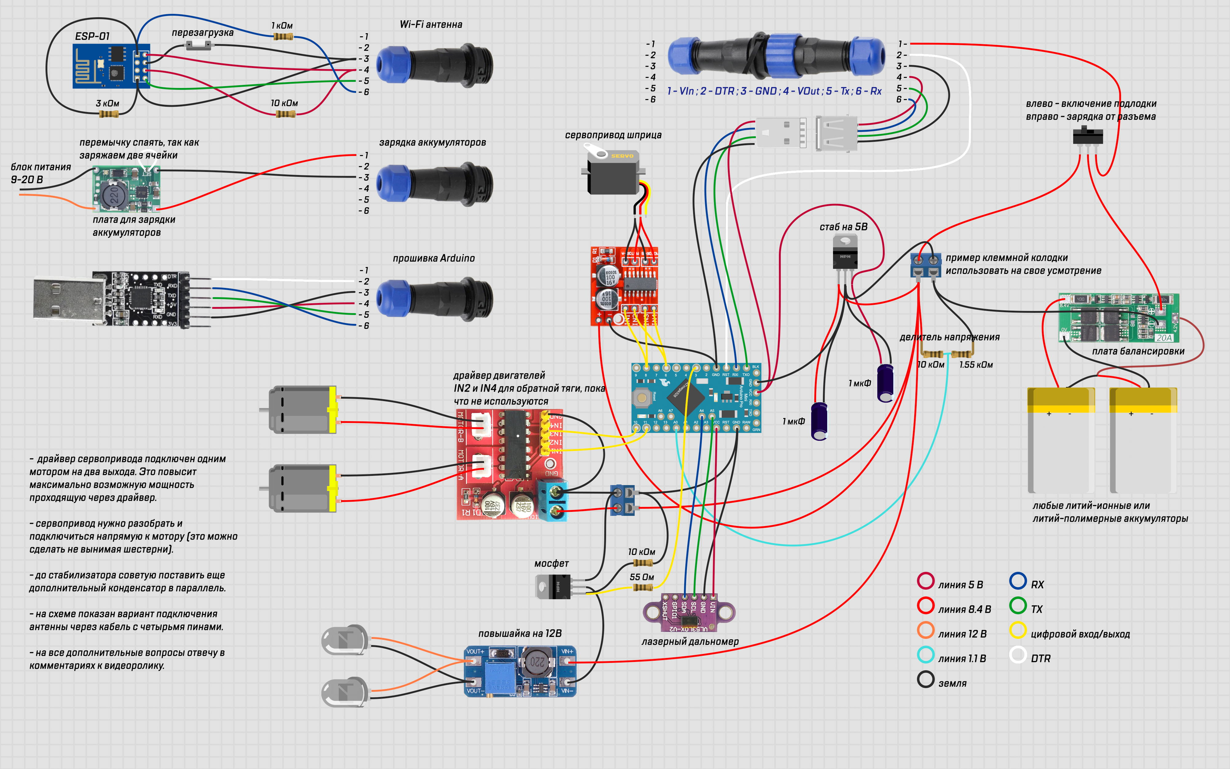 At first, a lot did not work out just for the reason that I collected everything on a breadboard. I just could not understand why this or that part of the circuit does not work. As a result, everything began to solder and positive test results were not long in coming.
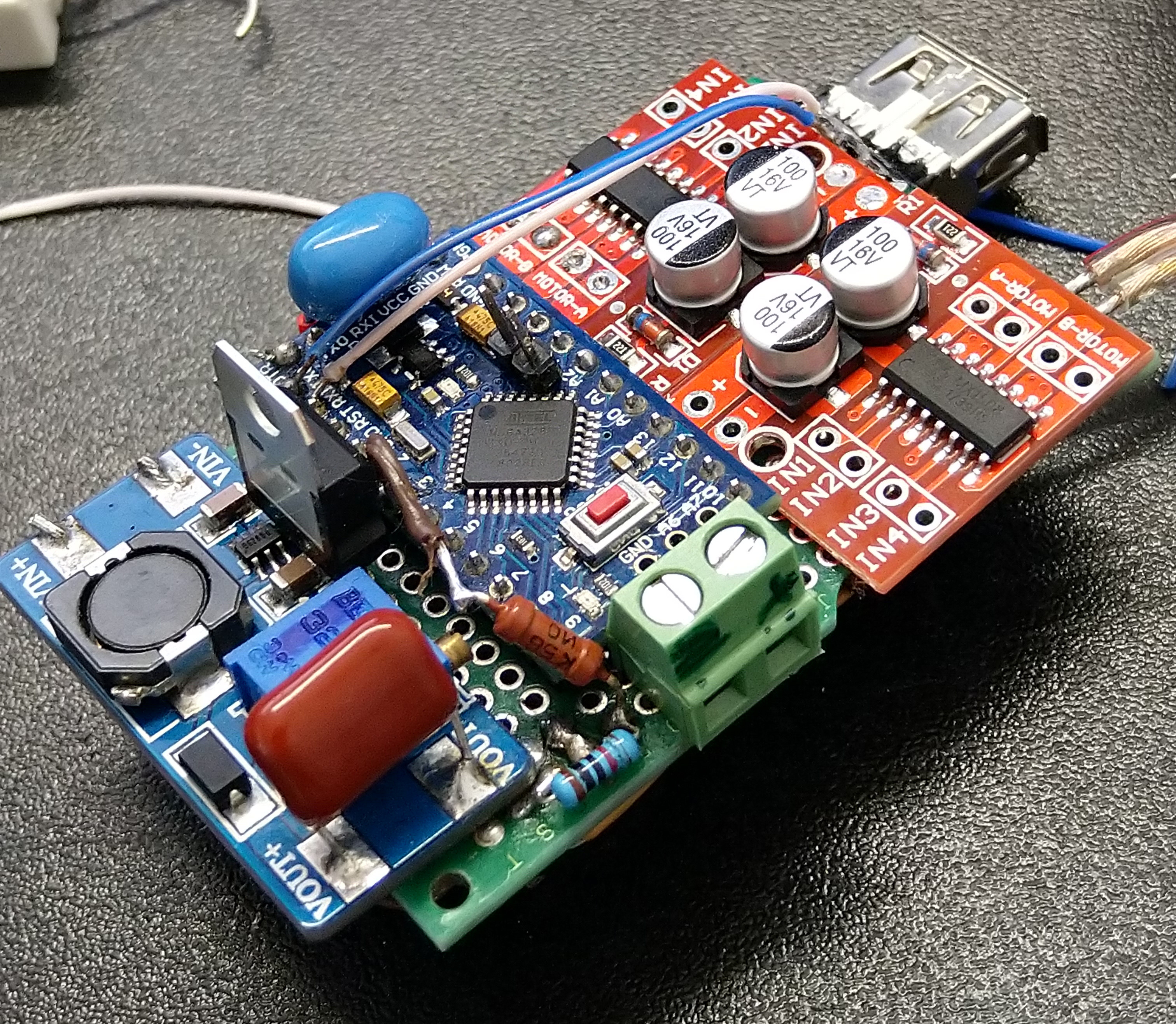 One of the interesting problems arose with the rangefinder. He has a good library, but if you set the accuracy mode to medium or high, then the whole sketch will slow down and the control will exit with a ping of 2000 ms minimum. Because of this, the range finder is in FAST mode, but its accuracy is still enough for our tasks.The next thing I came across is cable management. Case diameter 50 mm. It seems that this is a lot, until you start trying to place everything inside. I used straight overly bold cables designed for audio, which let me down a lot. I just wanted copper, because it is convenient to solder them, and so that they do not break, such as aluminum ones. Next time I will spend more time looking for good wires.
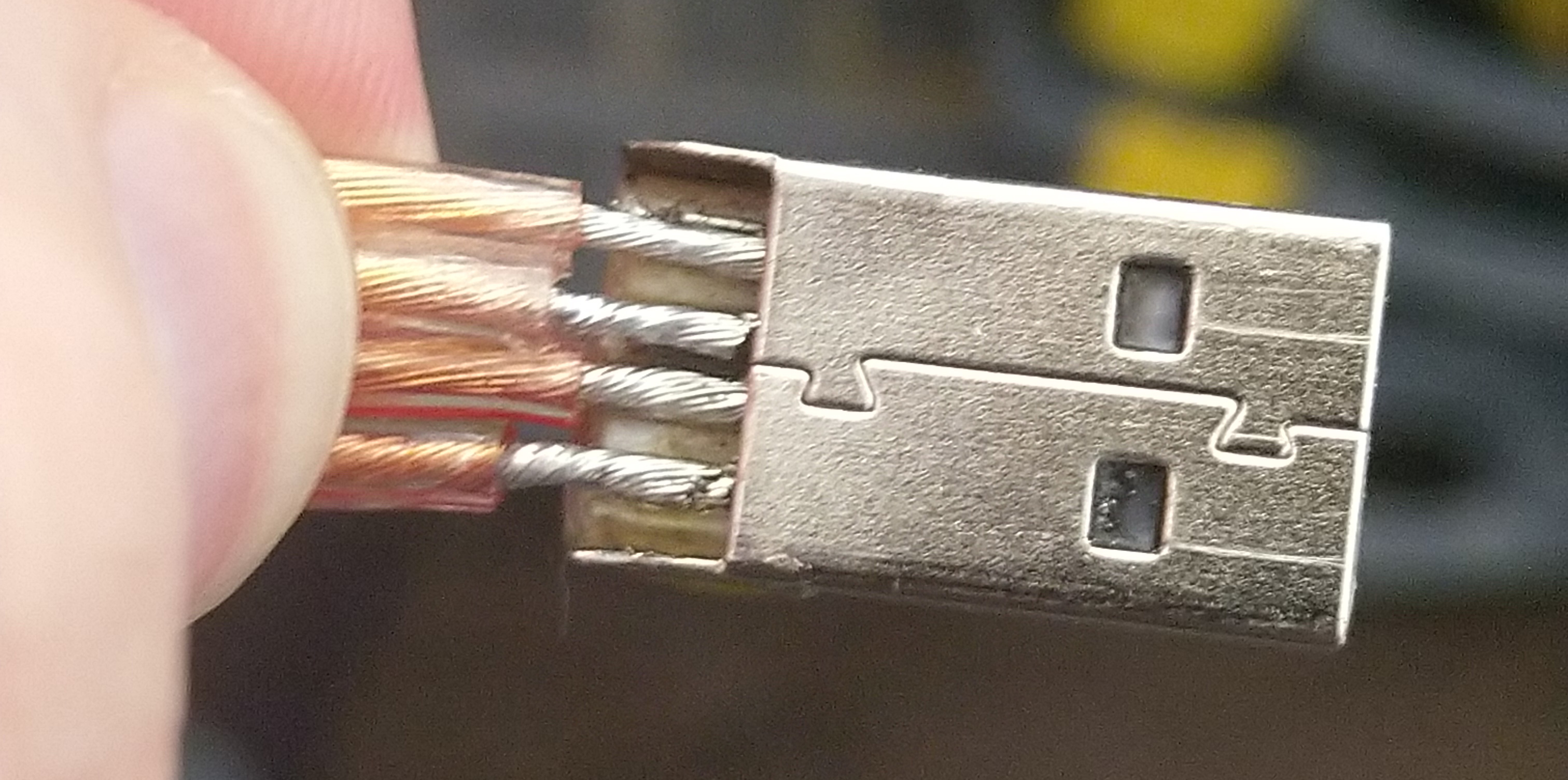
 Further difficulties arose only with the antenna.
Antenna
As an antenna, I decided to use esp8266 and control the submarine via a smartphone via Wi-Fi. Only the Chinese have a wide variety of modules based on ESP8266, I purchased three different ones, but I was able to connect and flash only one of them - ESP-01 .In theory, if you order now, they will already be with the necessary firmware. Management is via RemoteXY, and he needs a specific firmware version for AT commands. The problem of finding the right firmware to control via AT commands was solved only with the help of the RemoteXY guide. By the way, not advertising, I just liked the interface, and only then I found more convenient and well-developed interface designers for all kinds of IoT.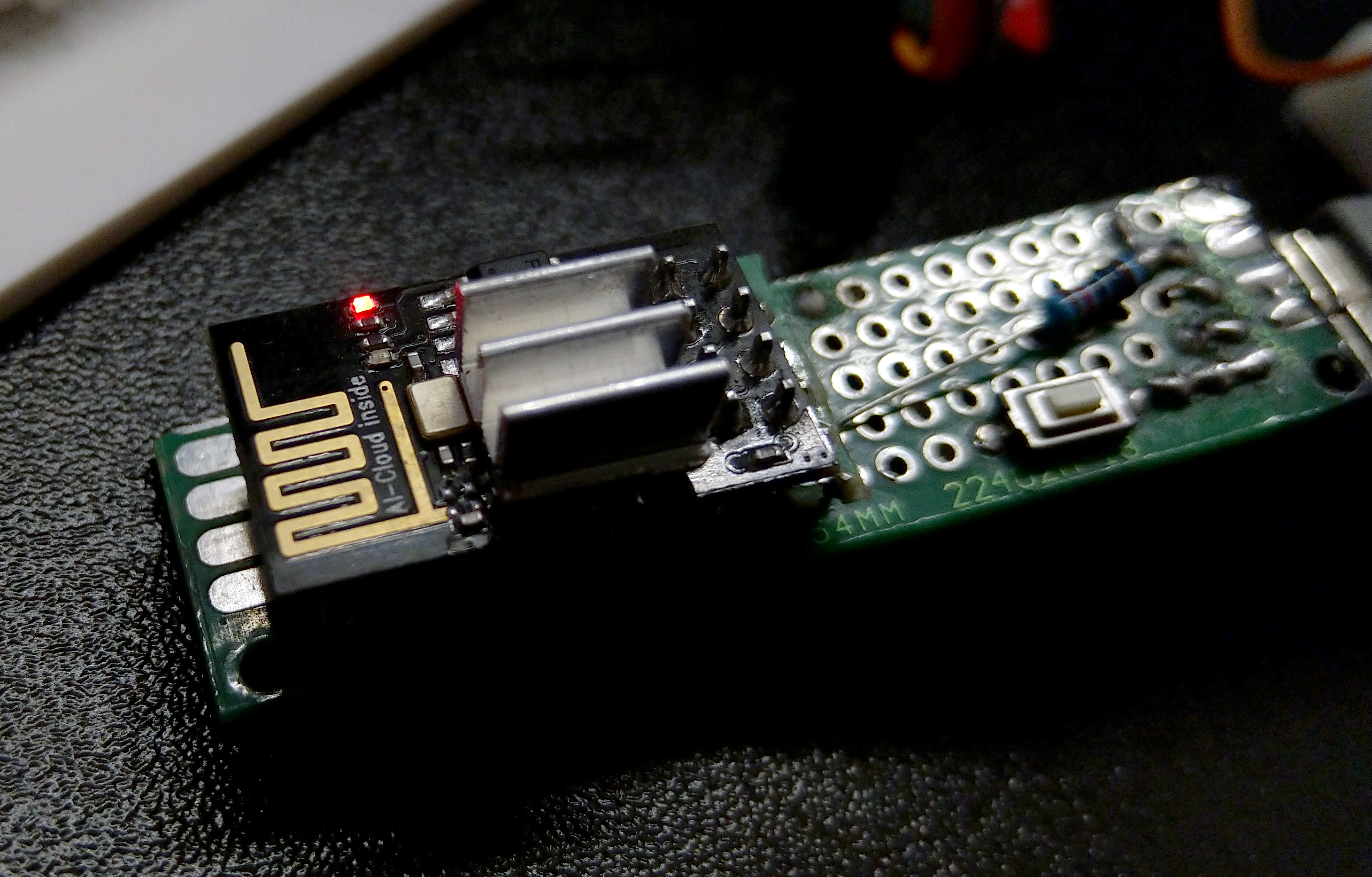 After successful firmware, I hung the module with the necessary components for work and soldered a USB connector for convenient connection. Integrated the USB mate into the cork from under a regular bottle and we got a simple wired antenna with the ability to change the case (bottle replacement).
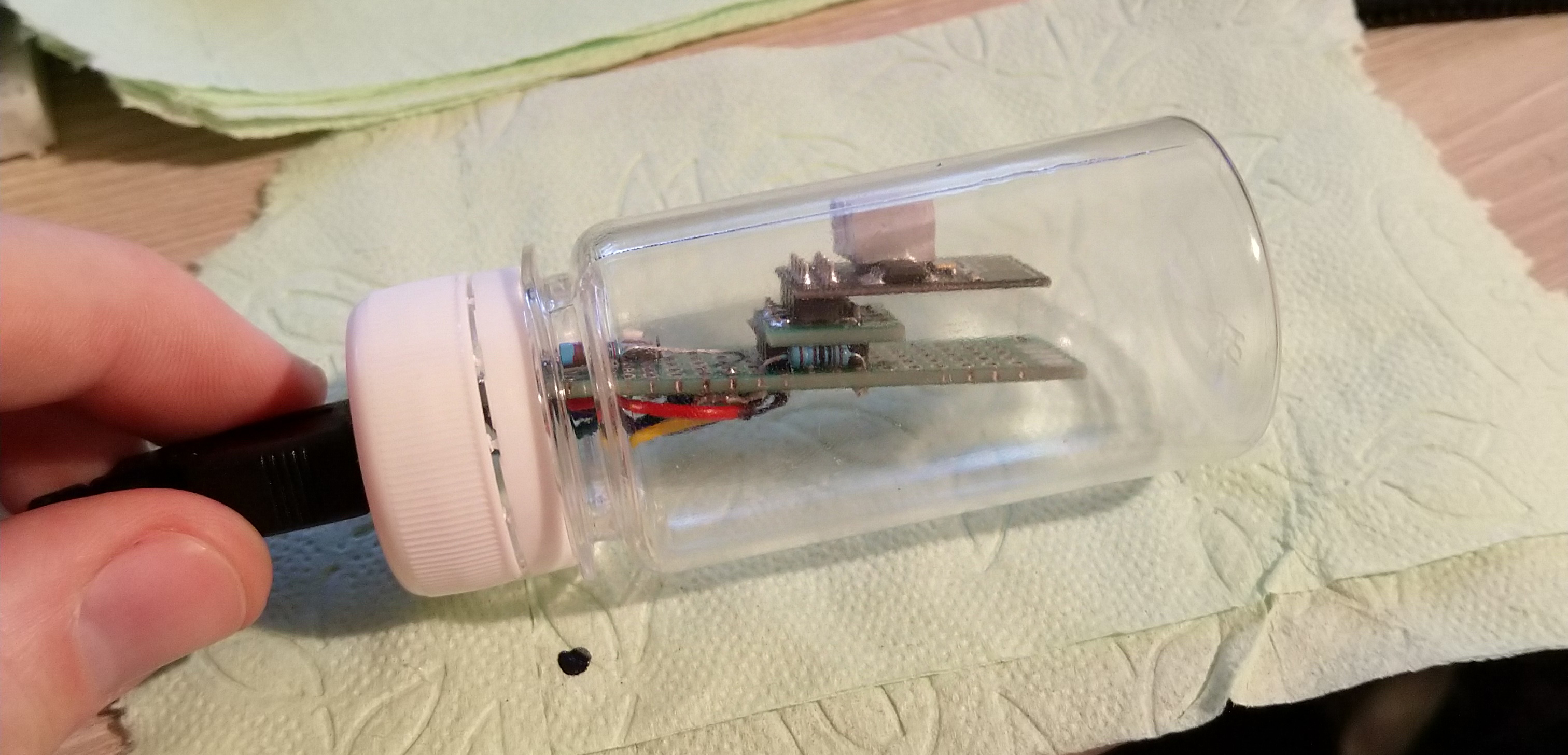 There were more problems besides firmware.The ESP-01 board should work from 3.3 V, and not from 5 V. Moreover, both the logic and the power supply. If I configured the logic through a level converter, then I was too lazy to mess with the power and I just stuck a small radiator child on the chip. From five volts it works fine, but it gets very hot. The radiator in the end helps not to burn the chip.
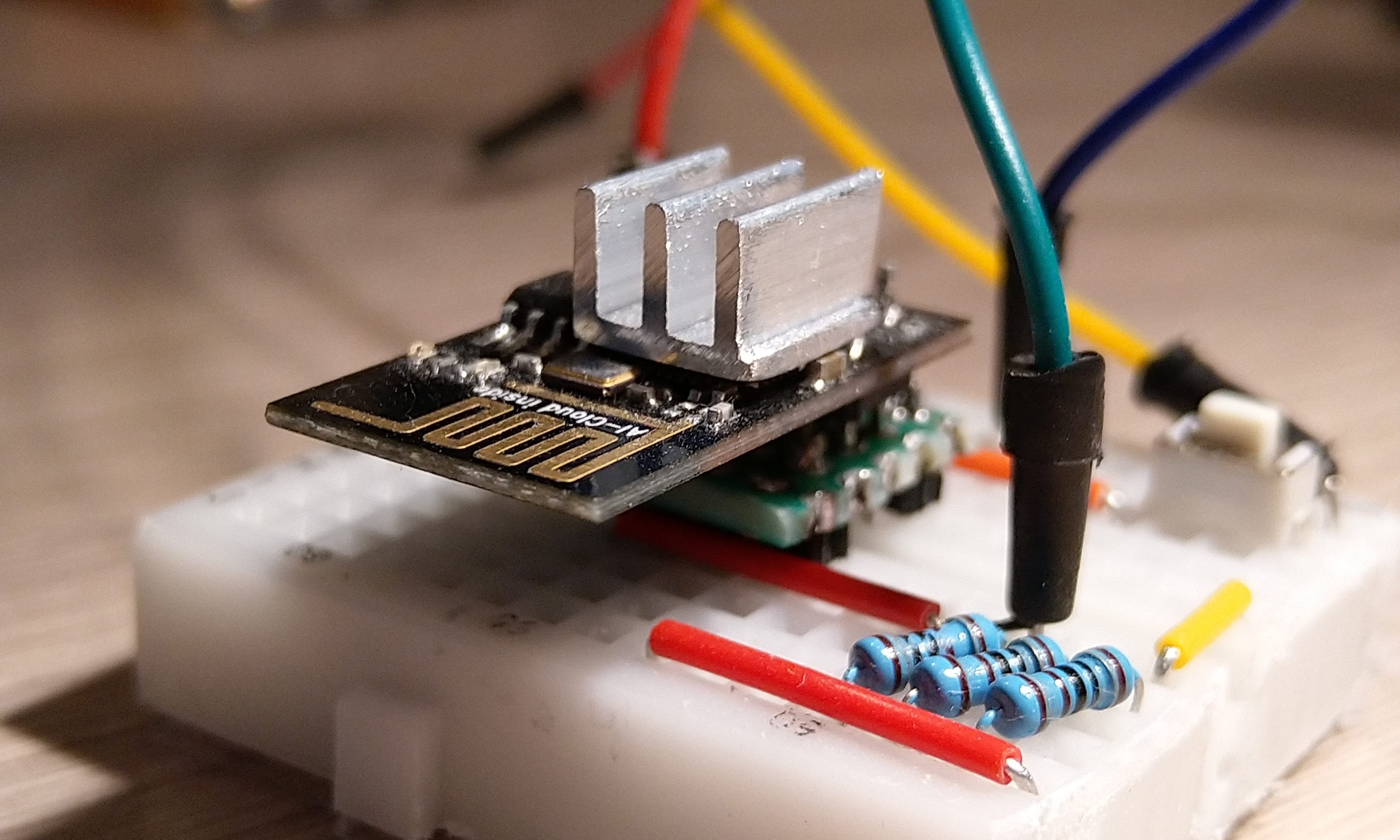 Another problem - I picked up the ideal cable for the sealed connector, but it is only 2 pins with shielding, while for the antenna you need 4 (power and RX and TX for communication between the antenna and Arduino on board).It turned out that it would not be possible to simply power up our antenna separately, since for ESP + Arduino to work, it was necessary to have a common ground. I had to use shielding as the ground near the cable, and add a separate battery to the antenna itself. Inconvenient, but it works. It’s easier, of course, to find a cable for 4 cores and feed the antenna with batteries from the submarine.
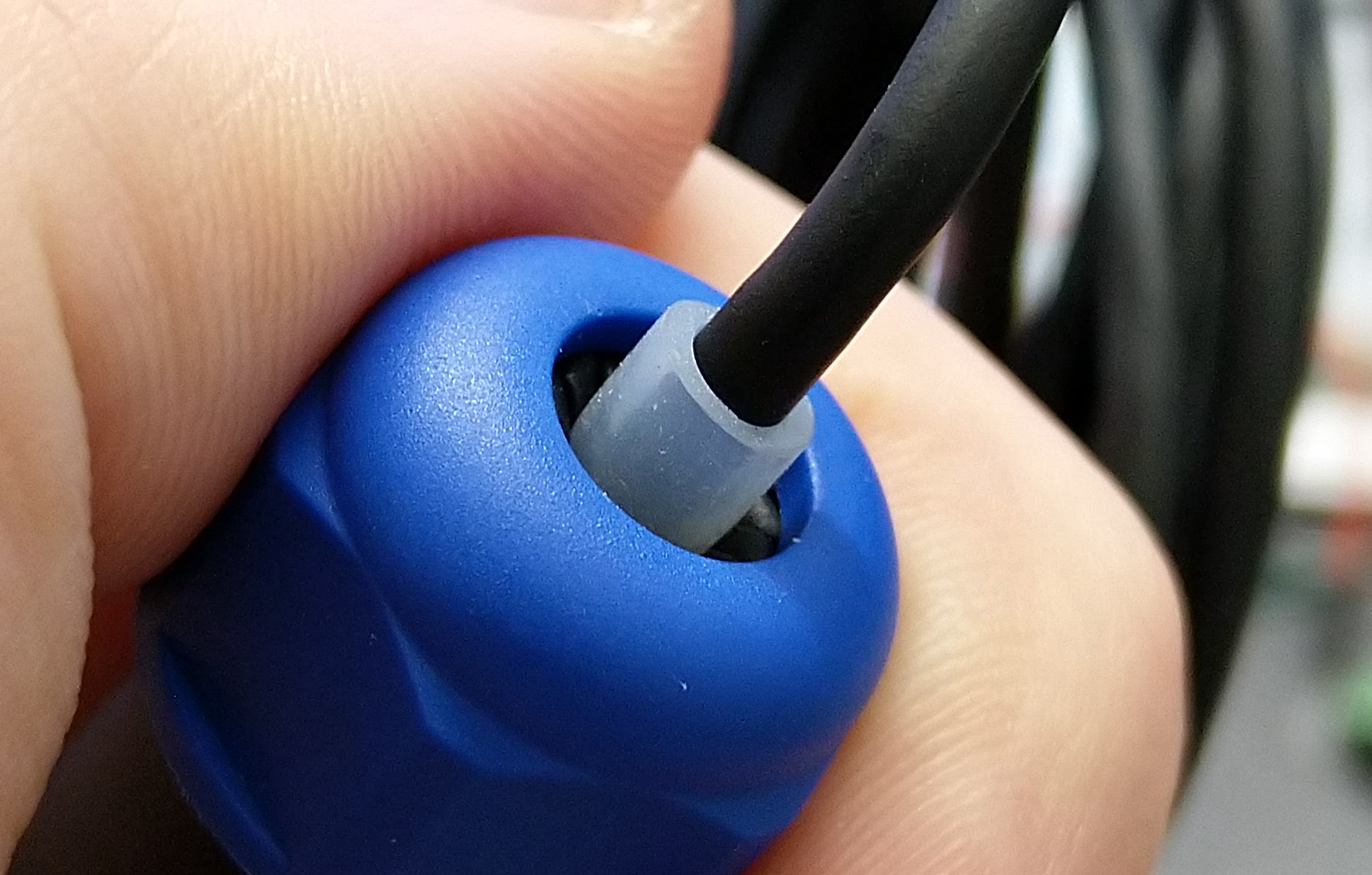 In the photo there is a good coincidence of the diameters of the cable, silicone tube and crimp hole at the sealed connector.
Management and firmware
Management is carried out through the interface from the smartphone. The interface was made up of ready-made modules directly on the site, received the source code of the interface, and then it remained just to bind the various elements of the interface to the actions inside the firmware.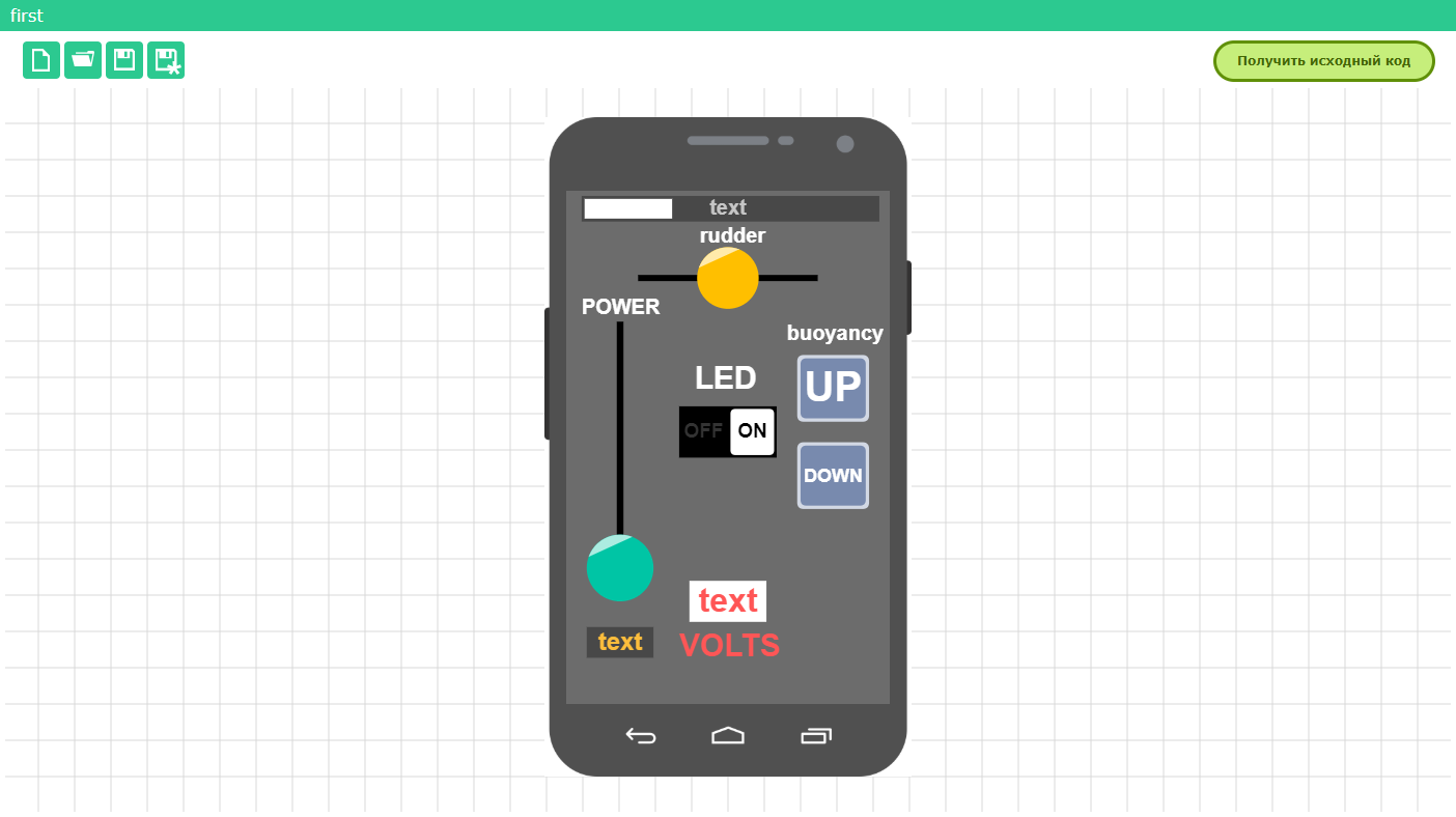 Before receiving the source code for the interface, you need to specify in the settings the type of wireless module with which the Arduino will interact. We only flash the Arduino itself - with the Wi-Fi module, communication goes on automatically through AT commands. An access point is created, connect to it from a smartphone and control it through a pre-installed application. The interface comes from Arduino, it is wired into the firmware and is recognized by the application itself in the smartphone.This was my very first code, I won’t leave it right here, because it uses only basic programming skills and basic mathematics. There were some difficult moments for me - I couldn’t do the usual logical operation the first time — so that at certain values the servo-drive of the syringe would be blocked for one-way movement.For example, when it comes to maximum water intake, the piston should stop backward, but should not block forward. And vice versa, when all the water is squeezed out, the piston should not go forward, but without any problems execute the return command.
 if ((RemoteXY.button_1 == 1) && (RemoteXY.button_2 == 0) && (val_f < 100)) {
pwm_UP = 1;
pwm_DOWN = 0;
}
else if ((RemoteXY.button_1 == 0) && (RemoteXY.button_2 == 1) && (val_f > 25)) {
pwm_UP = 0;
pwm_DOWN = 1;
}
else {
pwm_UP = 0;
pwm_DOWN = 0;
}
This is the logical construction in the end, where RemoteXY.button_ # are buttons in the interface for diving or surfacing.Also, from the difficult part for me in the code, this is a range finder filter (I took one of the simplest in the network), well, setting the values for the voltmeter. The filter was needed because of the aforementioned FAST mode on the rangefinder, the input values jumped a lot and the filter just helped to cope with it. But the voltmeter was useful for indicating the discharge of the batteries. The Arduino has a reference pin, and if no more than 1.1 volts is applied to it, then the Arduino will be able to accurately determine the supplied voltage to this pin. We convert 8.4 V after the voltage divider to 1.1 V. And this conversion turned out to be inaccurate, I had to experimentally correct the voltage value by adding a variable to the firmware.Testing
Testing was carried out on an abandoned quarry with relatively clean water. For tests, it was necessary to fix the camera and adjust the submarine trim (along with basic neutral buoyancy).The first task was solved simply by installing the right screw for the camera mount. To avoid camera rotations, a little clay was added.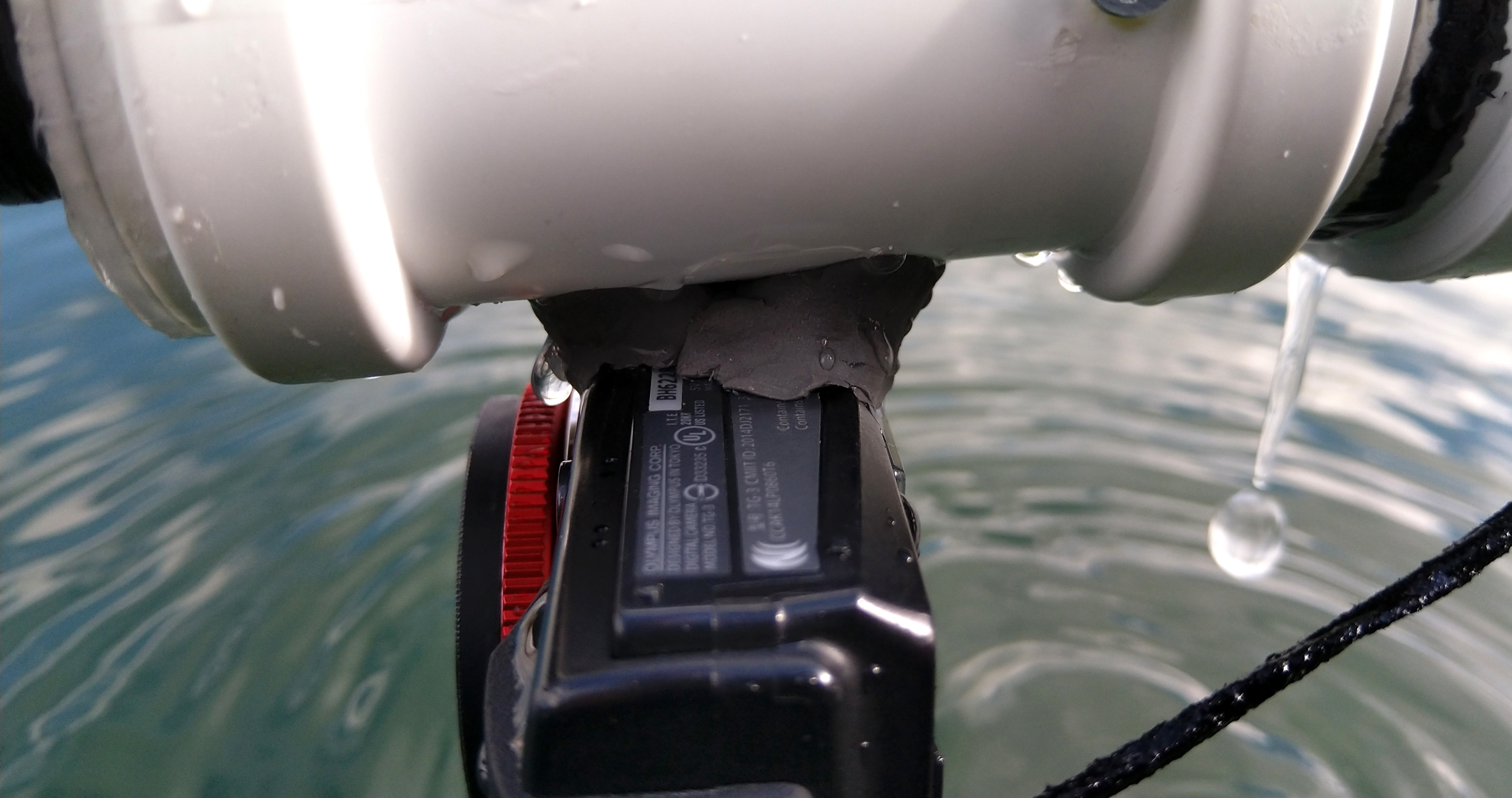 The trimmer was ruled by a bag, which turned out to be convenient to hook on the clamp, and already the clamp can be easily moved along the submarine. By the number of nuts in the bag, we set up neutral buoyancy, and then we quickly picked up the position of the clamp so that the submarine would not bite its nose. The decision on this option was made just before the trip to the quarry, there simply simply wasn’t time left to make an automatic trim trim system. It, in theory, is very easy to make by moving the load along the threaded rod. In the next submarine I’ll try exactly this option. Here, perhaps, is the whole submarine.I recorded two videos where I talk in more detail about the assembly and show the shots that I managed to shoot under water. Have a niceof viewing:Hope the material was interesting. Next will be experiments on the pressure chamber (to check the tightness of the apparatus) and tests of underwater oars. On them I will also prepare material in the form of an article, but already with graphs and comparisons of various decisions.