Hey.Some time ago, I put together a small soldering station that I wanted to talk about. This is an additional simplified soldering station to the main one, and of course cannot fully replace it.Main functions:1. Soldering iron. The code sets several temperature modes (100, 250 and 350 degrees), between which the Solder button switches. I do not need smooth adjustment here, I solder mainly at 250 degrees. It’s very convenient for me personally. To accurately maintain the temperature, a PID controller is used.Preset modes, pins, PID parameters can be changed in the 3_Solder file:struct {
static const byte termistor = A2;
static const byte pwm = 10;
static const byte use = 15;
int mode[4] = {0, 150, 250, 300};
byte set_solder = 0;
static const double PID_k[3] = {50, 5, 5};
static const byte PID_cycle = air.PID_cycle;
double PID_in;
double PID_set;
double PID_out;
unsigned long srednee;
} sol;
2. Hair dryer. Also, several temperature modes are set (switching by the Heat button), PID controller, fan shutdown only after the hair dryer cools to the preset temperature of 70 degrees.Preset modes, pins, PID parameters can be changed in the 2_Air file:struct {
static const byte termistor = A3;
static const byte heat = A0;
static const byte fan = 11;
int mode_heat[5] = {0, 300, 450, 600, 700};
byte set_air = 0;
static const double PID_k[3] = {10, 2, 10};
static const byte PID_cycle = 200;
double PID_in;
double PID_set;
double PID_out;
unsigned long time;
unsigned long srednee;
boolean OFF = 0;
} air;
Nuances:- The soldering iron used from his old station Lukey 936A, but with the replaced heating element on the Chinese copy of Hakko A1321.
- .
- .
- 220, .
- 220 .
- , , ( ). : , 426. : , , .
- , .
- 5 Arduino . 20 7805.
- 30 , . : 5 24.
Main components and components:1. Main board:- Arduino Pro mini,- touch buttons,- display from a Nokia 1202. Phone. Amplifier board:- Soldering iron thermistor amplifier,- Soldering iron heating field effect transistor,- Hair dryer thermocouple amplifier,- Field effect transistor turning on the fan of the hair dryer.3. The board of the triac moduleis an optocosmistor MOC3063,is a triac with a snubber chain.4. Power supply:- a power supply from a laptop 19V 3.5A,- a switch,- a stabilizer for powering the Arduino.5. Case.And now for more details on the nodes.1. The main board
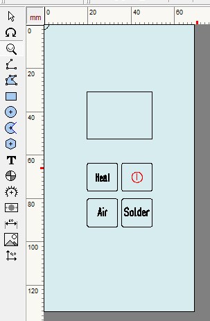
 Please note the name of the touch pads is different from the photo. The fact is that due to the refusal to adjust the fan speed, in the code I reassigned the button to turn on the hair dryer. At the very beginning, the speed control was implemented, but since the voltage of my PSU was 20V (increased by 1V by adding a variable resistor), and the fan was 24V, I decided to refuse. The signal from the TTP223 touch buttons (enabled in the Switch mode, 3.3V is applied to the TOG pin) is read by the Arduino. The display is connected via limiting resistors to match 5V and 3.3V logic. This solution is not entirely correct, but it has been working for several years in different devices.The main board is double-sided printed wiring. I left the metallization to the maximum to reduce the influence of interference, as well as to simplify the circuit of the touch buttons (for TTP223, a capacitor is required on entering the ground to reduce sensitivity. Without it, the button will work just when you approach your finger. But since I made this metallization a solid capacitor not required). Made a cutout for the display.
Board photo without parts On the upper side there are platforms of touch buttons, the front panel is glued, the display is soldered. The touch button pads and the display are connected to the bottom side via jumpers with a thin wire. Size resistors and capacitor 0603.Front panel manufacturing, 3 , FrontDesigner-3.0_rus, .
, , .
. . .
On the underside is the Arduino Pro mini and TTP223 touch-button chip.2. Amplifier board
Minor fixeasyJet , R11 ( ). , R3 , . . .

The soldering iron circuit consists of a differential amplifier with a resistive bridge and a field-effect transistor with a strapping.- To increase the “useful” range of the output signal with a low-resistance thermistor (in my case, in the Chinese copy of Hakko A1321 56 Ohm at 25 degrees, for comparison, 3D printers usually have a thermistor with a resistance of 100 kOhm at 25 degrees), a resistive bridge and a differential amplifier are used. To reduce interference, capacitors are installed in parallel with the thermistor and in the feedback circuit. This circuit is only needed for a thermistor, if there is a thermocouple in your soldering iron, then you need an amplifier circuit similar to that in the hairdryer circuit. No configuration required. Only measure the resistance of your thermistor at 25 degrees and if necessary change the 56 Ohm resistor to the measured one.
- The field effect transistor has been removed from the motherboard. A 100 kOhm resistor is needed so that the soldering iron itself does not turn on from pickups if the arduino, for example, turns off, ground the gate of the field-effect transistor. 220 ohm resistors to limit shutter charge current.
The hair dryer circuit consists of a non-inverting amplifier and a field effect transistor.- Amplifier: typical circuit. To reduce pickups, capacitors are parallel to the thermocouple and in the feedback circuit.
- The ME9926 field effect transistor does not have a harness, this is not accidental. The inclusion does not threaten anything, just a fan will spin. There is no limitation of the gate charge current either, since the shutter capacity is small.
The size of the resistors and capacitors is 0603, with the exception of the 56 Ohm resistor - 1206.No configuration is required.Nuances: the use of an operational amplifier LM321 (a single-channel analogue of LM358) for a differential amplifier is not optimal, since it is not a Rail-to-Rail operational amplifier, and the maximum output amplitude will be limited to 3.5-4 V at 5 V supply and the maximum temperature (at specified on the chart denominations) will be limited to around 426 degrees. I recommend using for example MCP6001. But you need to pay attention that depending on the letters at the end, the pinout is different: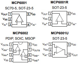
3. Triac module board
 Standard circuit with optocosmistor MOC3063. Since the MOC3063 itself determines the transition through the zero voltage of the 220V network, and the load is the inertia heater element, it makes no sense to use phase control, as well as additional zero control circuits.Nuances: you can simplify the scheme a little if you use a triac that does not require a snubber chain, they have snubberless.
4. Power supply
The choice was made in terms of overall dimensions and power output in the first place. I also slightly increased the output voltage to 20V. It was possible to do 22V, but when the soldering iron was turned on, the PSU protection worked.5. Case
The case was designed for my PSU, taking into account the size of the boards and subsequent printing on a 3D printer. The metal wasn’t even planned, a decent aluminum anodized case is a little expensive and scratched, and a bunch of other nuances. But bending yourself beautifully will not work.Connectors:1. Hair dryer - “aviation” GX16-8.2. Soldering iron - “aviation” GX12-6.Sources are here .That's all.PS I saved the first version in draft copies as a keepsake.