[Previous parts of the analysis: first and second and third .]Part 1. Cirrus Clouds
When the game takes place in open spaces, one of the factors determining the credibility of the world is the sky. Think about it - most of the time the sky literally takes about 40-50% of the entire screen. The sky is much more than a beautiful gradient. It has stars, the sun, the moon, and finally clouds.Although current trends seem to consist in volumetric rendering of clouds using raymarching (see this article ), the clouds in The Witcher 3 are completely texture-based. I already examined them before, but it turned out that with them everything is more complicated than I originally expected. If you followed my series of articles, then you know that there is a difference between the Blood and Wine DLC and the rest of the game. And, as you might guess, there are some changes in the work with clouds in the DLC.The Witcher 3 has several layers of clouds. Depending on the weather, it can only be cirrus clouds , high cumulus clouds , possibly a few clouds from the family of layered clouds (for example, during a storm). In the end, there may be no clouds at all.Some layers differ in terms of the textures and shaders used to render them. Obviously, this affects the complexity and length of the assembler code for the pixel shader.Despite all this diversity, there are some common patterns that can be observed when rendering clouds in Witcher 3. First, they all render in a proactive pass, and this is the perfect choice. All of them use mixing (see below). This makes it much easier to control how a separate layer covers the sky - this is affected by the alpha value from the pixel shader.More interestingly, some layers are rendered twice with the same parameters.After looking at the code, I chose the shortest shader in order to (1) most likely perform its full reverse engineering, (2) figure out all its aspects.I took a closer look at the cirrus clouds from Witcher 3: Blood and Wine.Here is an example frame:Before renderingAfter the first render passAfter the second render passIn this particular frame, cirrus clouds are the first layer in rendering. As you can see, it is rendered twice, which increases its brightness.Geometric and vertex shader
Before the pixel shader, we will briefly talk about the used geometric and vertex shaders. The mesh for displaying clouds is a bit like a regular sky dome:All vertices are in the interval [0-1], so to center the mesh on the point (0,0,0), scaling and deviation are used before converting to worldViewProj (we already know this pattern from the previous parts of the series). In the case of clouds, the mesh stretches strongly along the XY plane (the Z axis points up) to cover more space than the pyramid of visibility. The result is as follows:In addition, the mesh has normal and tangent vectors. The vertex shader also calculates the bi-tangent vector by the vector product - all three are displayed in normalized form. There is also a top calculation of fog (its color and brightness).Pixel shader
The pixel shader assembly code looks like this: ps_5_0
dcl_globalFlags refactoringAllowed
dcl_constantbuffer cb0[10], immediateIndexed
dcl_constantbuffer cb1[9], immediateIndexed
dcl_constantbuffer cb12[238], immediateIndexed
dcl_constantbuffer cb4[13], immediateIndexed
dcl_sampler s0, mode_default
dcl_resource_texture2d (float,float,float,float) t0
dcl_resource_texture2d (float,float,float,float) t1
dcl_input_ps linear v0.xyzw
dcl_input_ps linear v1.xyzw
dcl_input_ps linear v2.w
dcl_input_ps linear v3.xyzw
dcl_input_ps linear v4.xyz
dcl_input_ps linear v5.xyz
dcl_output o0.xyzw
dcl_temps 4
0: mul r0.xyz, cb0[9].xyzx, l(1.000000, 1.000000, -1.000000, 0.000000)
1: dp3 r0.w, r0.xyzx, r0.xyzx
2: rsq r0.w, r0.w
3: mul r0.xyz, r0.wwww, r0.xyzx
4: mul r1.xy, cb0[0].xxxx, cb4[5].xyxx
5: mad r1.xy, v1.xyxx, cb4[4].xyxx, r1.xyxx
6: sample_indexable(texture2d)(float,float,float,float) r1.xyzw, r1.xyxx, t0.xyzw, s0
7: add r1.xyz, r1.xyzx, l(-0.500000, -0.500000, -0.500000, 0.000000)
8: add r1.xyz, r1.xyzx, r1.xyzx
9: dp3 r0.w, r1.xyzx, r1.xyzx
10: rsq r0.w, r0.w
11: mul r1.xyz, r0.wwww, r1.xyzx
12: mul r2.xyz, r1.yyyy, v3.xyzx
13: mad r2.xyz, v5.xyzx, r1.xxxx, r2.xyzx
14: mov r3.xy, v1.zwzz
15: mov r3.z, v3.w
16: mad r1.xyz, r3.xyzx, r1.zzzz, r2.xyzx
  17: dp3_sat r0.x, r0.xyzx, r1.xyzx
  18: add r0.y, -cb4[2].x, cb4[3].x
  19: mad r0.x, r0.x, r0.y, cb4[2].x
20: dp2 r0.y, -cb0[9].xyxx, -cb0[9].xyxx
21: rsq r0.y, r0.y
22: mul r0.yz, r0.yyyy, -cb0[9].xxyx
  23: add r1.xyz, -v4.xyzx, cb1[8].xyzx
  24: dp3 r0.w, r1.xyzx, r1.xyzx
  25: rsq r1.z, r0.w
  26: sqrt r0.w, r0.w
27: add r0.w, r0.w, -cb4[7].x
28: mul r1.xy, r1.zzzz, r1.xyxx
29: dp2_sat r0.y, r0.yzyy, r1.xyxx
30: add r0.y, r0.y, r0.y
31: min r0.y, r0.y, l(1.000000)
32: add r0.z, -cb4[0].x, cb4[1].x
33: mad r0.z, r0.y, r0.z, cb4[0].x
34: mul r0.x, r0.x, r0.z
35: log r0.x, r0.x
36: mul r0.x, r0.x, l(2.200000)
37: exp r0.x, r0.x
38: add r1.xyz, cb12[236].xyzx, -cb12[237].xyzx
39: mad r1.xyz, r0.yyyy, r1.xyzx, cb12[237].xyzx
40: mul r2.xyz, r0.xxxx, r1.xyzx
41: mad r0.xyz, -r1.xyzx, r0.xxxx, v0.xyzx
42: mad r0.xyz, v0.wwww, r0.xyzx, r2.xyzx
43: add r1.x, -cb4[7].x, cb4[8].x
44: div_sat r0.w, r0.w, r1.x
45: mul r1.x, r1.w, cb4[9].x
46: mad r1.y, -cb4[9].x, r1.w, r1.w
47: mad r0.w, r0.w, r1.y, r1.x
48: mul r1.xy, cb0[0].xxxx, cb4[11].xyxx
49: mad r1.xy, v1.xyxx, cb4[10].xyxx, r1.xyxx
50: sample_indexable(texture2d)(float,float,float,float) r1.x, r1.xyxx, t1.xyzw, s0
51: mad r1.x, r1.x, cb4[12].x, -cb4[12].x
52: mad_sat r1.x, cb4[12].x, v2.w, r1.x
53: mul r0.w, r0.w, r1.x
54: mul_sat r0.w, r0.w, cb4[6].x
55: mul o0.xyz, r0.wwww, r0.xyzx
56: mov o0.w, r0.w
57: ret
Two seamless textures are input. One of them contains a normal map ( xyz channels ) and a cloud shape (channel a ). The second is noise to distort the shape.Normal Map, CD Projekt Red PropertyCloud Shape, Property CD Projekt RedNoise texture, property of CD Projekt RedThe main buffer of constants with cloud parameters is cb4. For this frame, it has the following meanings:In addition, other values from other cbuffers are used. Do not worry, we will consider them too.Z-direction inverted sunlight
The first thing that happens in the shader is the calculation of the normalized direction of sunlight inverted along the Z axis: 0: mul r0.xyz, cb0[9].xyzx, l(1.000000, 1.000000, -1.000000, 0.000000)
1: dp3 r0.w, r0.xyzx, r0.xyzx
2: rsq r0.w, r0.w
3: mul r0.xyz, r0.wwww, r0.xyzx
float3 invertedSunlightDir = normalize(lightDir * float3(1, 1, -1) );
As mentioned earlier, the Z axis is directed upward, and cb0 [9] is the direction of sunlight. This vector is aimed at the sun - it is important! You can verify this by writing a simple computational shader that runs a simple NdotL, and inserting it into the deferred shader pass.Cloud Texture Sampling
The next step is to compute texcoords to sample the cloud texture, unpack the normal vector and normalize it. 4: mul r1.xy, cb0[0].xxxx, cb4[5].xyxx
5: mad r1.xy, v1.xyxx, cb4[4].xyxx, r1.xyxx
6: sample_indexable(texture2d)(float,float,float,float) r1.xyzw, r1.xyxx, t0.xyzw, s0
7: add r1.xyz, r1.xyzx, l(-0.500000, -0.500000, -0.500000, 0.000000)
8: add r1.xyz, r1.xyzx, r1.xyzx
9: dp3 r0.w, r1.xyzx, r1.xyzx
10: rsq r0.w, r0.w
float2 cloudTextureUV = Texcoords * textureScale + elapsedTime * speedFactors;
float4 cloudTextureValue = texture0.Sample( sampler0, cloudTextureUV ).rgba;
float3 normalMap = cloudTextureValue.xyz;
float cloudShape = cloudTextureValue.a;
float3 unpackedNormal = (normalMap - 0.5) * 2.0;
unpackedNormal = normalize(unpackedNormal);
Let's deal with it gradually.To get the movement of the clouds, we need elapsed time in seconds ( cb [0] .x ) multiplied by the speed coefficient, which affects how fast the clouds move across the sky ( cb4 [5] .xy ).As I said earlier, UVs are stretched along the geometry of the sky dome, and we also need texture scaling factors that affect the size of the clouds ( cb4 [4] .xy ).The final formula is:samplingUV = Input.TextureUV * textureScale + time * speedMultiplier;
After sampling all 4 channels, we have a normal map (rgb channels) and a cloud shape (channel a).To unpack the normal map from the interval [0; 1] in the interval [-1; 1] we use the following formula:unpackedNormal = (packedNormal - 0.5) * 2.0;
You can also use this:unpackedNormal = packedNormal * 2.0 - 1.0;
Finally, we normalize the unpacked normal vector.Overlay normals
Having the normal vectors, the tangent and the bi-tangent vectors from the vertex shader, and the normal vector from the normal map, we normally map the normals. 11: mul r1.xyz, r0.wwww, r1.xyzx
12: mul r2.xyz, r1.yyyy, v3.xyzx
13: mad r2.xyz, v5.xyzx, r1.xxxx, r2.xyzx
14: mov r3.xy, v1.zwzz
15: mov r3.z, v3.w
16: mad r1.xyz, r3.xyzx, r1.zzzz, r2.xyzx
float3 SkyTangent = Input.Tangent;
float3 SkyNormal = (float3( Input.Texcoords.zw, Input.param3.w ));
float3 SkyBitangent = Input.param3.xyz;
float3x3 TBN = float3x3(SkyTangent, SkyBitangent, SkyNormal);
float3 finalNormal = (float3)mul( unpackedNormal, (TBN) );
Brightness (1)
In the next step, NdotL calculation is applied and this affects the amount of illumination of a specific pixel.Consider the following assembler code: 17: dp3_sat r0.x, r0.xyzx, r1.xyzx
18: add r0.y, -cb4[2].x, cb4[3].x
19: mad r0.x, r0.x, r0.y, cb4[2].x
Here is the visualization of NdotL on the frame in question:This scalar product (with saturation) is used to interpolate between minIntensity and maxIntensity. Thanks to this, parts of the clouds illuminated by sunlight will be brighter.
float NdotL = saturate( dot(invertedSunlightDir, finalNormal) );
float intensity1 = lerp( param1Min, param1Max, NdotL );
Brightness (2)
There is another factor affecting the brightness of the clouds.Clouds located in that part of the sky where the sun is, should be more highlighted. To do this, we calculate the gradient based on the XY plane.This gradient is used to calculate linear interpolation between the min / max values, similar to what happens in part (1).That is, theoretically, we can ask to darken the clouds located on the opposite side of the sun, but this does not happen in this particular frame, because param2Min and param2Max ( cb4 [0] .x and cb4 [1] .x ) are set to 1.0f. 20: dp2 r0.y, -cb0[9].xyxx, -cb0[9].xyxx
21: rsq r0.y, r0.y
22: mul r0.yz, r0.yyyy, -cb0[9].xxyx
23: add r1.xyz, -v4.xyzx, cb1[8].xyzx
24: dp3 r0.w, r1.xyzx, r1.xyzx
25: rsq r1.z, r0.w
26: sqrt r0.w, r0.w
27: add r0.w, r0.w, -cb4[7].x
28: mul r1.xy, r1.zzzz, r1.xyxx
29: dp2_sat r0.y, r0.yzyy, r1.xyxx
30: add r0.y, r0.y, r0.y
31: min r0.y, r0.y, l(1.000000)
32: add r0.z, -cb4[0].x, cb4[1].x
33: mad r0.z, r0.y, r0.z, cb4[0].x
34: mul r0.x, r0.x, r0.z
35: log r0.x, r0.x
36: mul r0.x, r0.x, l(2.200000)
37: exp r0.x, r0.x
float2 lightDirXY = normalize( -lightDir.xy );
float3 vWorldToCamera = ( CameraPos - WorldPos );
float worldToCamera_distance = length(vWorldToCamera);
vWorldToCamera = normalize( vWorldToCamera );
float LdotV = saturate( dot(lightDirXY, vWorldToCamera.xy) );
float highlightedSkySection = saturate( 2*LdotV );
float intensity2 = lerp( param2Min, param2Max, highlightedSkySection );
float finalIntensity = pow( intensity2 *intensity1, 2.2);
At the very end, we multiply both brightnesses and raise the result to a power of 2.2.Cloud color
The calculation of the color of the clouds begins with obtaining from the buffer constants two values indicating the color of the clouds next to the sun and the clouds on the opposite side of the sky. Between them, linear interpolation is performed based on highlightedSkySection .Then the result is multiplied by finalIntensity .And in the end, the result is mixed with fog (for performance reasons, it was calculated by the vertex shader). 38: add r1.xyz, cb12[236].xyzx, -cb12[237].xyzx
39: mad r1.xyz, r0.yyyy, r1.xyzx, cb12[237].xyzx
40: mul r2.xyz, r0.xxxx, r1.xyzx
41: mad r0.xyz, -r1.xyzx, r0.xxxx, v0.xyzx
42: mad r0.xyz, v0.wwww, r0.xyzx, r2.xyzx
float3 cloudsColor = lerp( cloudsColorBack, cloudsColorFront, highlightedSunSection );
cloudsColor *= finalIntensity;
cloudsColor = lerp( cloudsColor, FogColor, FogAmount );
Make cirrus clouds more visible on the horizon
This is not very noticeable on the frame, but in fact this layer is more visible near the horizon than above Geralt's head. Here's how to do it.You could notice that when calculating the second brightness, we calculated the length of the vector worldToCamera : 23: add r1.xyz, -v4.xyzx, cb1[8].xyzx
24: dp3 r0.w, r1.xyzx, r1.xyzx
25: rsq r1.z, r0.w
26: sqrt r0.w, r0.w
Let's find the following occurrences of this length in the code: 26: sqrt r0.w, r0.w
27: add r0.w, r0.w, -cb4[7].x
...
43: add r1.x, -cb4[7].x, cb4[8].x
44: div_sat r0.w, r0.w, r1.x
Wow, what is it with us?cb [7] .x and cb [8] .x have the values 2000.0 and 7000.0.It turns out that this is the result of using the linstep function .She receives three parameters: min / max - interval and v - value.This works as follows: if v is in the interval [ min - max ], then the function returns linear interpolation in the interval [0.0 - 1.0]. On the other hand, if v is out of range, then linstep returns 0.0 or 1.0.A simple example:linstep( 1000.0, 2000.0, 999.0) = 0.0
linstep( 1000.0, 2000.0, 1500.0) = 0.5
linstep( 1000.0, 2000.0, 2000.0) = 1.0
That is, it is quite similar to the smoothstep from HLSL, except that in this case, instead of Hermitian interpolation, linear is performed.Linstep is not a feature in HLSL, but it is very useful. It is worth having it in your toolkit.
float linstep( float min, float max, float v )
{
return saturate( (v - min) / (max - min) );
}
Let's go back to Witcher 3: after calculating this indicator, reporting how far a particular part of the sky is from Geralt, we use it to weaken the brightness of the clouds: 45: mul r1.x, r1.w, cb4[9].x
46: mad r1.y, -cb4[9].x, r1.w, r1.w
47: mad r0.w, r0.w, r1.y, r1.x
float distanceAttenuation = linstep( fadeDistanceStart, fadeDistanceEnd, worldToCamera_distance );
float fadedCloudShape = closeCloudsHidingFactor * cloudShape;
cloudShape = lerp( fadedCloudShape, cloudShape, distanceAttenuation );
cloudShape is the .a channel from the first texture, and closeCloudsHidingFactor is a constant buffer value that controls the visibility of clouds above Geralt's head. In all the frames I tested, it was equal to 0.0, which is equivalent to the absence of clouds. As distanceAttenuation approaches 1.0 (the distance from the camera to the dome of the sky increases), the clouds become more visible.Noise texture sampling
Calculation of coordinates of sampling noise texture similar calculations for the texture of clouds, except that you use a different set of textureScale and speedMultiplier .Of course, a sampler with the wrap addressing mode enabled is used to sample all these textures . 48: mul r1.xy, cb0[0].xxxx, cb4[11].xyxx
49: mad r1.xy, v1.xyxx, cb4[10].xyxx, r1.xyxx
50: sample_indexable(texture2d)(float,float,float,float) r1.x, r1.xyxx, t1.xyzw, s0
float2 noiseTextureUV = Texcoords * textureScaleNoise + elapsedTime * speedFactorsNoise;
float noiseTextureValue = texture1.Sample( sampler0, noiseTextureUV ).x;
Putting It All Together
Having received the noise value, we must combine it with cloudShape.I had some problems understanding these lines, where there is param2.w (which is always 1.0) and noiseMult (has a value of 5.0, taken from the constant buffer).Be that as it may, the most important thing here is the final value of generalCloudsVisibility , which affects the visibility of the clouds.Take a look also at the final value of the noise. The output color of cloudsColor is multiplied by the final noise, which is also output to the alpha channel. 51: mad r1.x, r1.x, cb4[12].x, -cb4[12].x
52: mad_sat r1.x, cb4[12].x, v2.w, r1.x
53: mul r0.w, r0.w, r1.x
54: mul_sat r0.w, r0.w, cb4[6].x
55: mul o0.xyz, r0.wwww, r0.xyzx
56: mov o0.w, r0.w
57: ret
float noiseTextureValue = texture1.Sample( sampler0, noiseTextureUV ).x;
noiseTextureValue = noiseTextureValue * noiseMult - noiseMult;
float noiseValue = saturate( noiseMult * Input.param2.w + noiseTextureValue);
noiseValue *= cloudShape;
float finalNoise = saturate( noiseValue * generalCloudsVisibility);
return float4( cloudsColor*finalNoise, finalNoise );
Total
The finished result looks very believable.You can compare. The first picture is my shader, the second is the game shader:If you're curious, the shader is available here .Part 2. Fog
Fog can be implemented in various ways. However, the times when we could apply a simple distance-dependent fog and do away with it were forever in the past (most likely). Living in the world of programmable shaders has opened the door for new crazy, but more importantly, physically accurate and visually realistic solutions.Current trends in fog rendering are based on computational shaders (for details, see this presentation by Bart Wronsky).Despite the fact that this presentation appeared in 2014, and The Witcher 3 was released in 2015/2016, the fog in the last part of Geralt’s adventures is completely dependent on the screen and is implemented as a typical post-processing.Before we begin our next reverse engineering session, I must say that over the past year I tried to figure out the fog of Witcher 3 at least five times, and each time failed. The assembler code, as you will soon see, is quite complicated, and this makes the process of creating an readable fog shader on HLSL almost impossible.However, I managed to find a fog shader on the Internet that immediately attracted my attention due to its similarity to The Witcher 3 fog in terms of variable names and the general order of instructions. This shader was not exactly the same as in the game, so I had to rework it a bit. I want to say this that the main part of the HLSL code that you see here was, with two exceptions, not created / analyzed by me. Remember this.Here's the assembler code for the pixel fog shader - it's worth noting that it is the same for the entire game (the main part of 2015 and both DLCs): ps_5_0
dcl_globalFlags refactoringAllowed
dcl_constantbuffer cb3[2], immediateIndexed
dcl_constantbuffer cb12[214], immediateIndexed
dcl_resource_texture2d (float,float,float,float) t0
dcl_resource_texture2d (float,float,float,float) t1
dcl_resource_texture2d (float,float,float,float) t2
dcl_input_ps_siv v0.xy, position
dcl_output o0.xyzw
dcl_temps 7
0: ftou r0.xy, v0.xyxx
1: mov r0.zw, l(0, 0, 0, 0)
2: ld_indexable(texture2d)(float,float,float,float) r1.x, r0.xyww, t0.xyzw
3: mad r1.y, r1.x, cb12[22].x, cb12[22].y
4: lt r1.y, r1.y, l(1.000000)
5: if_nz r1.y
6: utof r1.yz, r0.xxyx
7: mul r2.xyzw, r1.zzzz, cb12[211].xyzw
8: mad r2.xyzw, cb12[210].xyzw, r1.yyyy, r2.xyzw
9: mad r1.xyzw, cb12[212].xyzw, r1.xxxx, r2.xyzw
10: add r1.xyzw, r1.xyzw, cb12[213].xyzw
11: div r1.xyz, r1.xyzx, r1.wwww
12: ld_indexable(texture2d)(float,float,float,float) r2.xyz, r0.xyww, t1.xyzw
  13:  ld_indexable(texture2d)(float,float,float,float) r0.x, r0.xyzw, t2.xyzw
  14:  max r0.x, r0.x, cb3[1].x
  15:  add r0.yzw, r1.xxyz, -cb12[0].xxyz
  16:  dp3 r1.x, r0.yzwy, r0.yzwy
  17:  sqrt r1.x, r1.x
  18:  add r1.y, r1.x, -cb3[0].x
  19:  add r1.zw, -cb3[0].xxxz, cb3[0].yyyw
  20:  div_sat r1.y, r1.y, r1.z
  21:  mad r1.y, r1.y, r1.w, cb3[0].z
  22:  add r0.x, r0.x, l(-1.000000)
  23:  mad r0.x, r1.y, r0.x, l(1.000000)
24: div r0.yzw, r0.yyzw, r1.xxxx
25: mad r1.y, r0.w, cb12[22].z, cb12[0].z
26: add r1.x, r1.x, -cb12[22].z
27: max r1.x, r1.x, l(0)
28: min r1.x, r1.x, cb12[42].z
29: mul r1.z, r0.w, r1.x
30: mul r1.w, r1.x, cb12[43].x
31: mul r1.zw, r1.zzzw, l(0.000000, 0.000000, 0.062500, 0.062500)
32: dp3 r0.y, cb12[38].xyzx, r0.yzwy
33: add r0.z, r0.y, cb12[42].x
34: add r0.w, cb12[42].x, l(1.000000)
35: div_sat r0.z, r0.z, r0.w
36: add r0.w, -cb12[43].z, cb12[43].y
37: mad r0.z, r0.z, r0.w, cb12[43].z
38: mul r0.w, abs(r0.y), abs(r0.y)
39: mad_sat r2.w, r1.x, l(0.002000), l(-0.300000)
40: mul r0.w, r0.w, r2.w
41: lt r0.y, l(0), r0.y
42: movc r3.xyz, r0.yyyy, cb12[39].xyzx, cb12[41].xyzx
43: add r3.xyz, r3.xyzx, -cb12[40].xyzx
44: mad r3.xyz, r0.wwww, r3.xyzx, cb12[40].xyzx
45: movc r4.xyz, r0.yyyy, cb12[45].xyzx, cb12[47].xyzx
46: add r4.xyz, r4.xyzx, -cb12[46].xyzx
47: mad r4.xyz, r0.wwww, r4.xyzx, cb12[46].xyzx
48: ge r0.y, r1.x, cb12[48].y
49: if_nz r0.y
50: add r0.y, r1.y, cb12[42].y
51: mul r0.w, r0.z, r0.y
52: mul r1.y, r0.z, r1.z
53: mad r5.xyzw, r1.yyyy, l(16.000000, 15.000000, 14.000000, 13.000000), r0.wwww
54: max r5.xyzw, r5.xyzw, l(0, 0, 0, 0)
55: add r5.xyzw, r5.xyzw, l(1.000000, 1.000000, 1.000000, 1.000000)
56: div_sat r5.xyzw, r1.wwww, r5.xyzw
57: add r5.xyzw, -r5.xyzw, l(1.000000, 1.000000, 1.000000, 1.000000)
58: mul r1.z, r5.y, r5.x
59: mul r1.z, r5.z, r1.z
60: mul r1.z, r5.w, r1.z
61: mad r5.xyzw, r1.yyyy, l(12.000000, 11.000000, 10.000000, 9.000000), r0.wwww
62: max r5.xyzw, r5.xyzw, l(0, 0, 0, 0)
63: add r5.xyzw, r5.xyzw, l(1.000000, 1.000000, 1.000000, 1.000000)
64: div_sat r5.xyzw, r1.wwww, r5.xyzw
65: add r5.xyzw, -r5.xyzw, l(1.000000, 1.000000, 1.000000, 1.000000)
66: mul r1.z, r1.z, r5.x
67: mul r1.z, r5.y, r1.z
68: mul r1.z, r5.z, r1.z
69: mul r1.z, r5.w, r1.z
70: mad r5.xyzw, r1.yyyy, l(8.000000, 7.000000, 6.000000, 5.000000), r0.wwww
71: max r5.xyzw, r5.xyzw, l(0, 0, 0, 0)
72: add r5.xyzw, r5.xyzw, l(1.000000, 1.000000, 1.000000, 1.000000)
73: div_sat r5.xyzw, r1.wwww, r5.xyzw
74: add r5.xyzw, -r5.xyzw, l(1.000000, 1.000000, 1.000000, 1.000000)
75: mul r1.z, r1.z, r5.x
76: mul r1.z, r5.y, r1.z
77: mul r1.z, r5.z, r1.z
78: mul r1.z, r5.w, r1.z
79: mad r5.xy, r1.yyyy, l(4.000000, 3.000000, 0.000000, 0.000000), r0.wwww
80: max r5.xy, r5.xyxx, l(0, 0, 0, 0)
81: add r5.xy, r5.xyxx, l(1.000000, 1.000000, 0.000000, 0.000000)
82: div_sat r5.xy, r1.wwww, r5.xyxx
83: add r5.xy, -r5.xyxx, l(1.000000, 1.000000, 0.000000, 0.000000)
84: mul r1.z, r1.z, r5.x
85: mul r1.z, r5.y, r1.z
86: mad r0.w, r1.y, l(2.000000), r0.w
87: max r0.w, r0.w, l(0)
88: add r0.w, r0.w, l(1.000000)
89: div_sat r0.w, r1.w, r0.w
90: add r0.w, -r0.w, l(1.000000)
91: mul r0.w, r0.w, r1.z
92: mad r0.y, r0.y, r0.z, r1.y
93: max r0.y, r0.y, l(0)
94: add r0.y, r0.y, l(1.000000)
95: div_sat r0.y, r1.w, r0.y
96: add r0.y, -r0.y, l(1.000000)
97: mad r0.y, -r0.w, r0.y, l(1.000000)
98: add r0.z, r1.x, -cb12[48].y
99: mul_sat r0.z, r0.z, cb12[48].z
100: else
101: mov r0.yz, l(0.000000, 1.000000, 0.000000, 0.000000)
102: endif
103: log r0.y, r0.y
104: mul r0.w, r0.y, cb12[42].w
105: exp r0.w, r0.w
106: mul r0.y, r0.y, cb12[48].x
107: exp r0.y, r0.y
108: mul r0.yw, r0.yyyw, r0.zzzz
109: mad_sat r1.xy, r0.wwww, cb12[189].xzxx, cb12[189].ywyy
110: add r5.xyz, -r3.xyzx, cb12[188].xyzx
111: mad r5.xyz, r1.xxxx, r5.xyzx, r3.xyzx
112: add r0.z, cb12[188].w, l(-1.000000)
113: mad r0.z, r1.y, r0.z, l(1.000000)
114: mul_sat r5.w, r0.z, r0.w
115: lt r0.z, l(0), cb12[192].x
116: if_nz r0.z
117: mad_sat r1.xy, r0.wwww, cb12[191].xzxx, cb12[191].ywyy
118: add r6.xyz, -r3.xyzx, cb12[190].xyzx
119: mad r3.xyz, r1.xxxx, r6.xyzx, r3.xyzx
120: add r0.z, cb12[190].w, l(-1.000000)
121: mad r0.z, r1.y, r0.z, l(1.000000)
122: mul_sat r3.w, r0.z, r0.w
123: add r1.xyzw, -r5.xyzw, r3.xyzw
124: mad r5.xyzw, cb12[192].xxxx, r1.xyzw, r5.xyzw
125: endif
126: mul r0.z, r0.x, r5.w
127: mul r0.x, r0.x, r0.y
128: dp3 r0.y, l(0.333000, 0.555000, 0.222000, 0.000000), r2.xyzx
129: mad r1.xyz, r0.yyyy, r4.xyzx, -r2.xyzx
130: mad r0.xyw, r0.xxxx, r1.xyxz, r2.xyxz
131: add r1.xyz, -r0.xywx, r5.xyzx
132: mad r0.xyz, r0.zzzz, r1.xyzx, r0.xywx
133: else
134: mov r0.xyz, l(0, 0, 0, 0)
135: endif
136: mov o0.xyz, r0.xyzx
137: mov o0.w, l(1.000000)
138: ret
Honestly, the shader is quite long. Probably too long for an effective reverse engineering process.Here is an example of a sunset scene with fog:Let's take a look at the input:As for textures, we have a depth buffer, Ambient Occlusion, and an HDR color buffer.Inbound depth bufferIncoming ambient occlusionThe incoming HDR color buffer... and the result of applying the fog shader in this scene looks like this:HDR texture after applying fog.Depth buffer is used to recreate the position in the world. This is the standard pattern for Witcher 3 shaders.Having ambient occlusion data (if enabled) allows us to obscure the fog. A very clever idea, perhaps an obvious one, but I never thought of it that way. I will return to this aspect later.A shader starts by determining if a pixel is in the sky. In case the pixel lies in the sky (depth == 1.0), the shader returns black. If the pixel is in the scene (depth <1.0), then we recreate the position in the world using the depth buffer (lines 7-11) and continue to calculate the fog.The passage of fog occurs shortly after the delayed shading process. You may notice that some elements related to the forward run are not yet available. In this particular scene, deferred lighting volumes were applied, and after that we rendered Geralt's hair / face / eyes.The first thing you need to know about fog in “The Witcher 3”: it consists of two parts - “color of the fog” and “color of the atmosphere”. struct FogResult
{
float4 paramsFog;
float4 paramsAerial;
};
For each part there are three colors: front, middle and rear. That is, in the constant buffer there is such data as “FogColorFront”, “FogColorMiddle”, “AerialColorBack”, etc. ... Let's look at the incoming data:
float3 FogSunDir = cb12_v38.xyz;
float3 FogColorFront = cb12_v39.xyz;
float3 FogColorMiddle = cb12_v40.xyz;
float3 FogColorBack = cb12_v41.xyz;
float4 FogBaseParams = cb12_v42;
float4 FogDensityParamsScene = cb12_v43;
float4 FogDensityParamsSky = cb12_v44;
float3 AerialColorFront = cb12_v45.xyz;
float3 AerialColorMiddle = cb12_v46.xyz;
float3 AerialColorBack = cb12_v47.xyz;
float4 AerialParams = cb12_v48;
Before calculating the final colors, we need to calculate the vectors and scalar products. The shader has access to the pixel position in the world, camera position (cb12 [0] .xyz) and fog / lighting direction (cb12 [38] .xyz). This allows us to calculate the scalar product of the vector of the form and direction of the fog. float3 frag_vec = fragPosWorldSpace.xyz - customCameraPos.xyz;
float frag_dist = length(frag_vec);
float3 frag_dir = frag_vec / frag_dist;
float dot_fragDirSunDir = dot(GlobalLightDirection.xyz, frag_dir);
To calculate the mixing gradient, you need to use the square of the absolute scalar product, and then again multiply the result by some parameter that depends on the distance: float3 curr_col_fog;
float3 curr_col_aerial;
{
float _dot = dot_fragDirSunDir;
float _dd = _dot;
{
const float _distOffset = -150;
const float _distRange = 500;
const float _mul = 1.0 / _distRange;
const float _bias = _distOffset * _mul;
_dd = abs(_dd);
_dd *= _dd;
_dd *= saturate( frag_dist * _mul + _bias );
}
curr_col_fog = lerp( FogColorMiddle.xyz, (_dot>0.0f ? FogColorFront.xyz : FogColorBack.xyz), _dd );
curr_col_aerial = lerp( AerialColorMiddle.xyz, (_dot>0.0f ? AerialColorFront.xyz : AerialColorBack.xyz), _dd );
}
This code block makes it clear to us where these 0.002 and -0.300 came from. As we can see, the scalar product between the vectors of view and lighting is responsible for the choice between the “front” and “back” colors. Clever!Here is a visualization of the resulting final gradient (_dd).However, calculating the effect of the atmosphere / fog is much more complicated. As you can see, we have much more options than just rgb colors. They include, for example, scene density. We use raymarching (16 steps, and this is why the cycle can be expanded) to determine the size of the fog and the scale factor:Having a vector [camera ---> world], we can divide all its components into 16 - this will be one raymarching step. As we see below, only the .z (height) component ( curr_pos_z_step ) is involved in the calculations .Read more about the fog implemented by raymarching, for example, here . float fog_amount = 1;
float fog_amount_scale = 0;
[branch]
if ( frag_dist >= AerialParams.y )
{
float curr_pos_z_base = (customCameraPos.z + FogBaseParams.y) * density_factor;
float curr_pos_z_step = frag_step.z * density_factor;
[unroll]
for ( int i=16; i>0; --i )
{
fog_amount *= 1 - saturate( density_sample_scale / (1 + max( 0.0, curr_pos_z_base + (i) * curr_pos_z_step ) ) );
}
fog_amount = 1 - fog_amount;
fog_amount_scale = saturate( (frag_dist - AerialParams.y) * AerialParams.z );
}
FogResult ret;
ret.paramsFog = float4 ( curr_col_fog, fog_amount_scale * pow( abs(fog_amount), final_exp_fog ) );
ret.paramsAerial = float4 ( curr_col_aerial, fog_amount_scale * pow( abs(fog_amount), final_exp_aerial ) );
The amount of fog obviously depends on the height (components .z), at the end the amount of fog is raised to the degree of fog / atmosphere.final_exp_fog and final_exp_aerial are taken from the constant buffer; they allow you to control how the colors of fog and atmosphere affect the world with increasing altitude.Fog override
The shader I found did not have the following assembly code fragment: 109: mad_sat r1.xy, r0.wwww, cb12[189].xzxx, cb12[189].ywyy
110: add r5.xyz, -r3.xyzx, cb12[188].xyzx
111: mad r5.xyz, r1.xxxx, r5.xyzx, r3.xyzx
112: add r0.z, l(-1.000000), cb12[188].w
113: mad r0.z, r1.y, r0.z, l(1.000000)
114: mul_sat r5.w, r0.w, r0.z
115: lt r0.z, l(0.000000), cb12[192].x
116: if_nz r0.z
117: mad_sat r1.xy, r0.wwww, cb12[191].xzxx, cb12[191].ywyy
118: add r6.xyz, -r3.xyzx, cb12[190].xyzx
119: mad r3.xyz, r1.xxxx, r6.xyzx, r3.xyzx
120: add r0.z, l(-1.000000), cb12[190].w
121: mad r0.z, r1.y, r0.z, l(1.000000)
122: mul_sat r3.w, r0.w, r0.z
123: add r1.xyzw, -r5.xyzw, r3.xyzw
124: mad r5.xyzw, cb12[192].xxxx, r1.xyzw, r5.xyzw
125: endif
Judging by what I was able to understand, this is like redefining the color and the effect of fog:Most of the time, only one redefinition is performed (cb12_v192.x is 0.0), but in this particular case its value is ~ 0.22, so we do the second override.
#ifdef OVERRIDE_FOG
float fog_influence = ret.paramsFog.w;
float override1ColorScale = cb12_v189.x;
float override1ColorBias = cb12_v189.y;
float3 override1Color = cb12_v188.rgb;
float override1InfluenceScale = cb12_v189.z;
float override1InfluenceBias = cb12_v189.w;
float override1Influence = cb12_v188.w;
float override1ColorAmount = saturate(fog_influence * override1ColorScale + override1ColorBias);
float override1InfluenceAmount = saturate(fog_influence * override1InfluenceScale + override1InfluenceBias);
float4 paramsFogOverride;
paramsFogOverride.rgb = lerp(curr_col_fog, override1Color, override1ColorAmount );
float param1 = lerp(1.0, override1Influence, override1InfluenceAmount);
paramsFogOverride.w = saturate(param1 * fog_influence );
const float extraFogOverride = cb12_v192.x;
[branch]
if (extraFogOverride > 0.0)
{
float override2ColorScale = cb12_v191.x;
float override2ColorBias = cb12_v191.y;
float3 override2Color = cb12_v190.rgb;
float override2InfluenceScale = cb12_v191.z;
float override2InfluenceBias = cb12_v191.w;
float override2Influence = cb12_v190.w;
float override2ColorAmount = saturate(fog_influence * override2ColorScale + override2ColorBias);
float override2InfluenceAmount = saturate(fog_influence * override2InfluenceScale + override2InfluenceBias);
float4 paramsFogOverride2;
paramsFogOverride2.rgb = lerp(curr_col_fog, override2Color, override2ColorAmount);
float ov_param1 = lerp(1.0, override2Influence, override2InfluenceAmount);
paramsFogOverride2.w = saturate(ov_param1 * fog_influence);
paramsFogOverride = lerp(paramsFogOverride, paramsFogOverride2, extraFogOverride);
}
ret.paramsFog = paramsFogOverride;
#endif
Here is our finished price without redefining fog (first image), with one redefinition (second image) and double redefinition (third image, final result):Regulation of ambient occlusion
The shader I found also did not use ambient occlusion at all. Let's take a look at the texture of AO again and the code that interests us: 13: ld_indexable(texture2d)(float,float,float,float) r0.x, r0.xyzw, t2.xyzw
14: max r0.x, r0.x, cb3[1].x
15: add r0.yzw, r1.xxyz, -cb12[0].xxyz
16: dp3 r1.x, r0.yzwy, r0.yzwy
17: sqrt r1.x, r1.x
18: add r1.y, r1.x, -cb3[0].x
19: add r1.zw, -cb3[0].xxxz, cb3[0].yyyw
20: div_sat r1.y, r1.y, r1.z
21: mad r1.y, r1.y, r1.w, cb3[0].z
22: add r0.x, r0.x, l(-1.000000)
23: mad r0.x, r1.y, r0.x, l(1.000000)
Perhaps this scene is not the best example, because we do not see the details on a distant island. However, let's take a look at the constant buffer, which is used to set the ambient occlusion value:We start by loading AO from the texture, then execute the max instruction. In this scene, cb3_v1.x is very high (0.96888), which makes the AO very weak.The next part of the code calculates the distance between the positions of the camera and the pixels in the world.I believe that the code sometimes speaks for itself, so let's look at HLSL, which does the bulk of this setup: float AdjustAmbientOcclusion(in float inputAO, in float worldToCameraDistance)
{
const float aoDistanceStart = cb3_v0.x;
const float aoDistanceEnd = cb3_v0.y;
const float aoStrengthStart = cb3_v0.z;
const float aoStrengthEnd = cb3_v0.w;
float aoDistanceIntensity = linstep( aoDistanceStart, aoDistanceEnd, worldToCameraDistance );
float aoStrength = lerp(aoStrengthStart, aoStrengthEnd, aoDistanceIntensity);
float adjustedAO = lerp(1.0, inputAO, aoStrength);
return adjustedAO;
}
The calculated distance between the camera and the world is used for the linstep function. We already know this function, it appeared in the cirrus cloud shader.As you can see, in the constant buffer we have the AO start / end distance values. The output of linstep affects the strength of the AO (as well as from cbuffer), and the strength affects the output of the AO.A brief example: the pixel is far, for example, the distance is 500.linstep returns 1.0;aoStrength is equal to aoStrengthEnd;This results in an AO return, which is approximately 77% (final force) of the input value.The incoming AO for this function was previously subjected to the max operation.Putting it all together
Having received the color and effect for the color of the fog and the color of the atmosphere, you can finally combine them.We start by attenuating the effect with the resulting AO: ...
FogResult fog = CalculateFog( worldPos, CameraPosition, fogStart, ao, false );
fog.paramsFog.w *= ao;
fog.paramsAerial.w *= ao;
outColor = ApplyFog(fog, colorHDR);
All the magic happens in the ApplyFog function : float3 ApplyFog(FogResult fog, float3 color)
{
const float3 LuminanceFactors = float3(0.333f, 0.555f, 0.222f);
float3 aerialColor = dot(LuminanceFactors, color) * fog.paramsAerial.xyz;
color = lerp(color, aerialColor, fog.paramsAerial.w);
color = lerp(color, fog.paramsFog.xyz, fog.paramsFog.w);
return color.xyz;
}
First, we calculate the luminosity of pixels:Then we multiply it by the color of the atmosphere:Then we combine the HDR color with the color of the atmosphere:The last step is to combine the intermediate result with the color of the fog:That's all!Some debugging screenshots
Atmospheric effectAtmosphere colorFog effectFog colorFinished scene without fogReady-made scene with fog onlyThe finished scene is just the main fogReady-made scene again with all the fog for ease of comparisonTotal
I think you can understand a lot of the above, if you look at the shader, it is here .I can say with pleasure that this shader is exactly the same as the original one - it makes me very happy.In general, the final result is highly dependent on the values passed to the shader. This is not a “magical” solution that gives perfect colors for the output, it requires many iterations and artists to make the final result look decent. I think it can be a long process, but after you complete it, the result will be very convincing, just like this sunset scene.The Witcher 3 Sky Shader also uses fog calculations to create a smooth transition of colors near the horizon. However, a different set of density coefficients is passed to the sky shader.Let me remind you - most of this shader was not created / analyzed by me. All acknowledgments should be sent to CD PROJEKT RED. Support them, they do an excellent job.Part 3. Shooting Stars
In The Witcher 3 there is a small but curious detail - shooting stars. Interestingly, they do not seem to be in the Blood and Wine DLC.In the video you can see how they look:Let's see how we managed to get this effect.As you can see, the body of a shooting star is much brighter than the tail. This is an important property that we will use later.Our agenda is quite familiar: first I will describe the general properties, then I will talk about topics related to geometry, and in the end we will move on to the pixel shader, where the most interesting things are happening.1. General overview
Briefly describe what is happening.Shooting stars are drawn in a proactive passage, immediately after the dome of the sky, sky and moon:DrawIndexed (720) - the dome of the sky,DrawIndexed (2160) - the sphere for the sky / moon,DrawIndexed (36) - is irrelevant, looks like a parallelepiped of the occlusion of the sun (?)DrawIndexed (12) - the shooting starDrawIndexedInstanced (1116, 1) - cirrus cloudsLike cirrus clouds , each shooting star is drawn twice in a row.Before the first draw callResult of the first draw callResult of the second draw callIn addition, as in many elements of the preemptive pass of this game, the following mixing state is used:2. Geometry
From the point of view of geometry, the first thing to mention is that each shooting star is represented by a thin quadrilateral with texcoords: 4 vertices, 6 indices. This is the simplest quad possible.Approximate quad of a shooting star.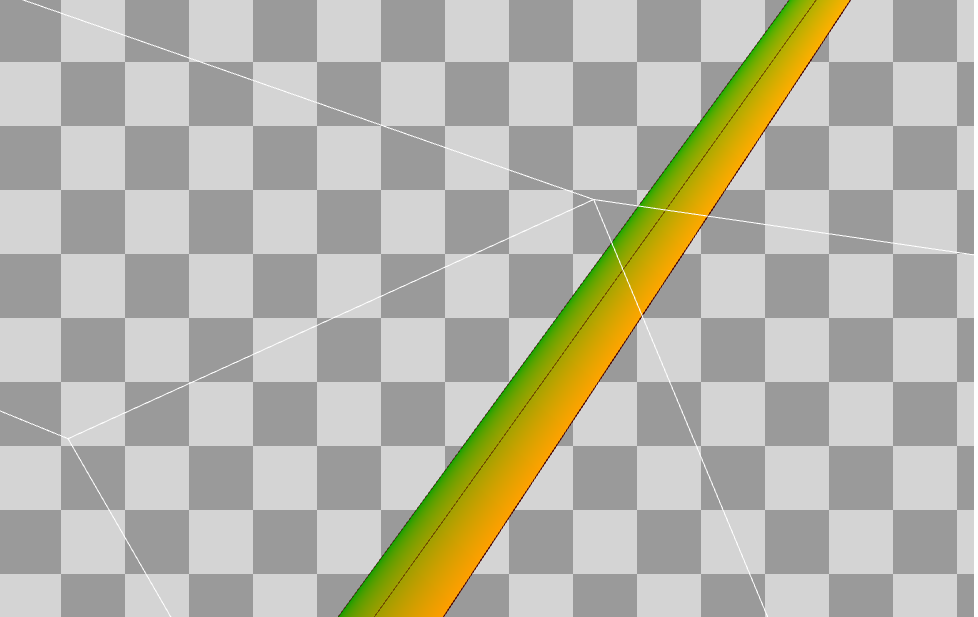 Even closer is the approximate quad of a shooting star. You can see the wireframe display of a line denoting two triangles.Wait a minute , but there is DrawIndexed (12) ! Does this mean that we draw two shooting stars at the same time?Yes.In this frame, one of the shooting stars is completely outside the pyramid of visibility.Let's look at the assembler code for the vertex shader:
 vs_5_0
dcl_globalFlags refactoringAllowed
dcl_constantbuffer cb1[9], immediateIndexed
dcl_constantbuffer cb2[3], immediateIndexed
dcl_constantbuffer cb12[193], immediateIndexed
dcl_input v0.xyz
dcl_input v1.xyzw
dcl_input v2.xy
dcl_input v3.xy
dcl_input v4.xy
dcl_input v5.xyz
dcl_input v6.x
dcl_input v7.x
dcl_output o0.xyzw
dcl_output o1.xyzw
dcl_output o2.xy
dcl_output o3.xyzw
dcl_output_siv o4.xyzw, position
dcl_temps 5
0: mov r0.xyz, v0.xyzx
1: mov r0.w, l(1.000000)
2: dp4 r1.x, r0.xyzw, cb2[0].xyzw
3: dp4 r1.y, r0.xyzw, cb2[1].xyzw
4: dp4 r1.z, r0.xyzw, cb2[2].xyzw
5: add r0.x, v2.x, v2.y
6: add r0.y, -v2.y, v2.x
   7: add r2.xyz, -r1.zxyz, cb1[8].zxyz
   8: dp3 r0.z, r2.xyzx, r2.xyzx
   9: rsq r0.z, r0.z
  10: mul r2.xyz, r0.zzzz, r2.xyzx
  11: dp3 r0.z, v5.xyzx, v5.xyzx
  12: rsq r0.z, r0.z
  13: mul r3.xyz, r0.zzzz, v5.xyzx
  14: mul r4.xyz, r2.xyzx, r3.yzxy
  15: mad r2.xyz, r2.zxyz, r3.zxyz, -r4.xyzx
  16: dp3 r0.z, r2.xyzx, r2.xyzx
  17: rsq r0.z, r0.z
  18: mul r2.xyz, r0.zzzz, r2.xyzx
  19: mad r0.z, v7.x, v6.x, l(1.000000)
  20: mul r3.xyz, r0.zzzz, r3.xyzx
  21: mul r3.xyz, r3.xyzx, v3.xxxx
  22: mul r2.xyz, r2.xyzx, v3.yyyy
  23: mad r0.xzw, r3.xxyz, r0.xxxx, r1.xxyz
  24: mad r0.xyz, r2.xyzx, r0.yyyy, r0.xzwx
  25: mov r0.w, l(1.000000)
  26: dp4 o4.x, r0.xyzw, cb1[0].xyzw
  27: dp4 o4.y, r0.xyzw, cb1[1].xyzw
  28: dp4 o4.z, r0.xyzw, cb1[2].xyzw
  29: dp4 o4.w, r0.xyzw, cb1[3].xyzw
30: add r0.xyz, r0.xyzx, -cb12[0].xyzx
31: dp3 r0.w, r0.xyzx, r0.xyzx
32: sqrt r0.w, r0.w
33: div r0.xyz, r0.xyzx, r0.wwww
34: add r0.w, r0.w, -cb12[22].z
35: max r0.w, r0.w, l(0)
36: min r0.w, r0.w, cb12[42].z
37: dp3 r0.x, cb12[38].xyzx, r0.xyzx
38: mul r0.y, abs(r0.x), abs(r0.x)
39: mad_sat r1.x, r0.w, l(0.002000), l(-0.300000)
40: mul r0.y, r0.y, r1.x
41: lt r1.x, l(0), r0.x
42: movc r1.yzw, r1.xxxx, cb12[39].xxyz, cb12[41].xxyz
43: add r1.yzw, r1.yyzw, -cb12[40].xxyz
44: mad r1.yzw, r0.yyyy, r1.yyzw, cb12[40].xxyz
45: movc r2.xyz, r1.xxxx, cb12[45].xyzx, cb12[47].xyzx
46: add r2.xyz, r2.xyzx, -cb12[46].xyzx
47: mad o0.xyz, r0.yyyy, r2.xyzx, cb12[46].xyzx
48: ge r0.y, r0.w, cb12[48].y
49: if_nz r0.y
50: mad r0.y, r0.z, cb12[22].z, cb12[0].z
51: mul r0.z, r0.w, r0.z
52: mul r0.z, r0.z, l(0.062500)
53: mul r1.x, r0.w, cb12[43].x
54: mul r1.x, r1.x, l(0.062500)
55: add r0.x, r0.x, cb12[42].x
56: add r2.x, cb12[42].x, l(1.000000)
57: div_sat r0.x, r0.x, r2.x
58: add r2.x, -cb12[43].z, cb12[43].y
59: mad r0.x, r0.x, r2.x, cb12[43].z
60: add r0.y, r0.y, cb12[42].y
61: mul r2.x, r0.x, r0.y
62: mul r0.z, r0.x, r0.z
63: mad r3.xyzw, r0.zzzz, l(16.000000, 15.000000, 14.000000, 13.000000), r2.xxxx
64: max r3.xyzw, r3.xyzw, l(0, 0, 0, 0)
65: add r3.xyzw, r3.xyzw, l(1.000000, 1.000000, 1.000000, 1.000000)
66: div_sat r3.xyzw, r1.xxxx, r3.xyzw
67: add r3.xyzw, -r3.xyzw, l(1.000000, 1.000000, 1.000000, 1.000000)
68: mul r2.y, r3.y, r3.x
69: mul r2.y, r3.z, r2.y
70: mul r2.y, r3.w, r2.y
71: mad r3.xyzw, r0.zzzz, l(12.000000, 11.000000, 10.000000, 9.000000), r2.xxxx
72: max r3.xyzw, r3.xyzw, l(0, 0, 0, 0)
73: add r3.xyzw, r3.xyzw, l(1.000000, 1.000000, 1.000000, 1.000000)
74: div_sat r3.xyzw, r1.xxxx, r3.xyzw
75: add r3.xyzw, -r3.xyzw, l(1.000000, 1.000000, 1.000000, 1.000000)
76: mul r2.y, r2.y, r3.x
77: mul r2.y, r3.y, r2.y
78: mul r2.y, r3.z, r2.y
79: mul r2.y, r3.w, r2.y
80: mad r3.xyzw, r0.zzzz, l(8.000000, 7.000000, 6.000000, 5.000000), r2.xxxx
81: max r3.xyzw, r3.xyzw, l(0, 0, 0, 0)
82: add r3.xyzw, r3.xyzw, l(1.000000, 1.000000, 1.000000, 1.000000)
83: div_sat r3.xyzw, r1.xxxx, r3.xyzw
84: add r3.xyzw, -r3.xyzw, l(1.000000, 1.000000, 1.000000, 1.000000)
85: mul r2.y, r2.y, r3.x
86: mul r2.y, r3.y, r2.y
87: mul r2.y, r3.z, r2.y
88: mul r2.y, r3.w, r2.y
89: mad r2.zw, r0.zzzz, l(0.000000, 0.000000, 4.000000, 3.000000), r2.xxxx
90: max r2.zw, r2.zzzw, l(0, 0, 0, 0)
91: add r2.zw, r2.zzzw, l(0.000000, 0.000000, 1.000000, 1.000000)
92: div_sat r2.zw, r1.xxxx, r2.zzzw
93: add r2.zw, -r2.zzzw, l(0.000000, 0.000000, 1.000000, 1.000000)
94: mul r2.y, r2.z, r2.y
95: mul r2.y, r2.w, r2.y
96: mad r2.x, r0.z, l(2.000000), r2.x
97: max r2.x, r2.x, l(0)
98: add r2.x, r2.x, l(1.000000)
99: div_sat r2.x, r1.x, r2.x
100: add r2.x, -r2.x, l(1.000000)
101: mul r2.x, r2.x, r2.y
102: mad r0.x, r0.y, r0.x, r0.z
103: max r0.x, r0.x, l(0)
104: add r0.x, r0.x, l(1.000000)
105: div_sat r0.x, r1.x, r0.x
106: add r0.x, -r0.x, l(1.000000)
107: mad r0.x, -r2.x, r0.x, l(1.000000)
108: add r0.y, r0.w, -cb12[48].y
109: mul_sat r0.y, r0.y, cb12[48].z
110: else
111: mov r0.xy, l(1.000000, 0.000000, 0.000000, 0.000000)
112: endif
113: log r0.x, r0.x
114: mul r0.z, r0.x, cb12[42].w
115: exp r0.z, r0.z
116: mul r0.z, r0.z, r0.y
117: mul r0.x, r0.x, cb12[48].x
118: exp r0.x, r0.x
119: mul o0.w, r0.x, r0.y
120: mad_sat r0.xy, r0.zzzz, cb12[189].xzxx, cb12[189].ywyy
121: add r2.xyz, -r1.yzwy, cb12[188].xyzx
122: mad r2.xyz, r0.xxxx, r2.xyzx, r1.yzwy
123: add r0.x, cb12[188].w, l(-1.000000)
124: mad r0.x, r0.y, r0.x, l(1.000000)
125: mul_sat r2.w, r0.x, r0.z
126: lt r0.x, l(0), cb12[192].x
127: if_nz r0.x
128: mad_sat r0.xy, r0.zzzz, cb12[191].xzxx, cb12[191].ywyy
129: add r3.xyz, -r1.yzwy, cb12[190].xyzx
130: mad r1.xyz, r0.xxxx, r3.xyzx, r1.yzwy
131: add r0.x, cb12[190].w, l(-1.000000)
132: mad r0.x, r0.y, r0.x, l(1.000000)
133: mul_sat r1.w, r0.x, r0.z
134: add r0.xyzw, -r2.xyzw, r1.xyzw
135: mad o1.xyzw, cb12[192].xxxx, r0.xyzw, r2.xyzw
136: else
137: mov o1.xyzw, r2.xyzw
138: endif
139: mov o3.xyzw, v1.xyzw
140: mov o2.xy, v4.yxyy
141: ret
Here, the calculation of fog can immediately attract attention (lines 30-138). Calculation of fog top makes sense for performance reasons. In addition, we do not need such accuracy of fog - meteoroids usually fly over Geralt's head and do not reach the horizon.The atmospheric parameters (rgb = color, a = influence) are stored in o0.xyzw, and the fog parameters in o1.xyzw.o2.xy (line 140) is just texcoords.o3.xyzw (line 139) is irrelevant.Now let's say a few words about calculating a position in the world. Vertex shaders perform billboarding . First of all, incoming data for billboards comes from the vertex buffer - let's take a look at them.The first data is Position:As mentioned above, here we have 2 quad-a: 8 vertices, 12 indices.But why is the position the same for every quad? Quite simple - this is the position of the center of the quad.Further, each vertex has an offset from the center to the edge of the quad:This means that every shooting star has a size of (400, 3) units in world space. (on the XY plane, in Witcher 3, the Z axis is directed up)The last element that each vertex has is a unit direction vector in world space that controls the motion of a shooting star:Since the data comes from the CPU, it is difficult to understand how it is calculated.Now let's move on to the billboarding code. The idea is quite simple - first you get a unit vector from the center of the quad to the camera: 7: add r2.xyz, -r1.zxyz, cb1[8].zxyz
8: dp3 r0.z, r2.xyzx, r2.xyzx
9: rsq r0.z, r0.z
10: mul r2.xyz, r0.zzzz, r2.xyzx
Then we get a single tangent vector that controls the motion of the shooting star.Given that this vector is already normalized on the CPU side, this normalization is redundant. 11: dp3 r0.z, v5.xyzx, v5.xyzx
12: rsq r0.z, r0.z
13: mul r3.xyz, r0.zzzz, v5.xyzx
If there are two vectors, a vector product is used to determine the bi-tangent vector perpendicular to both incoming vectors. 14: mul r4.xyz, r2.xyzx, r3.yzxy
15: mad r2.xyz, r2.zxyz, r3.zxyz, -r4.xyzx
16: dp3 r0.z, r2.xyzx, r2.xyzx
17: rsq r0.z, r0.z
18: mul r2.xyz, r0.zzzz, r2.xyzx
Now we have normalized vectors tangent (r3.xyz) and bitangent (r2.xyz).Let's introduce Xsize and Ysize corresponding to the incoming element TEXCOORD1, so for example (-200, 1.50).The final calculation of the position in world space is performed as follows: 19: mad r0.z, v7.x, v6.x, l(1.000000)
20: mul r3.xyz, r0.zzzz, r3.xyzx
21: mul r3.xyz, r3.xyzx, v3.xxxx
22: mul r2.xyz, r2.xyzx, v3.yyyy
23: mad r0.xzw, r3.xxyz, r0.xxxx, r1.xxyz
24: mad r0.xyz, r2.xyzx, r0.yyyy, r0.xzwx
25: mov r0.w, l(1.000000)
Given that r0.x, r0.y and r0.z are equal to 1.0, the final calculation is simplified:worldSpacePosition = quadCenter + tangent * Xsize + bitangent * YsizeThe last part is a simple multiplication of a position in world space by a view-projection matrix to obtain SV_Position: 26: dp4 o4.x, r0.xyzw, cb1[0].xyzw
27: dp4 o4.y, r0.xyzw, cb1[1].xyzw
28: dp4 o4.z, r0.xyzw, cb1[2].xyzw
29: dp4 o4.w, r0.xyzw, cb1[3].xyzw
3. Pixel Shader
As stated in the General Overview section, the following blending state is used: where SrcColor and SrcAlpha are the .rgb and .a components from the pixel shader, respectively , and DestColor is the .rgb color currently in rendertarget. The main indicator that controls transparency is SrcAlpha . Many proactive game shaders calculate it as opacity and apply it at the end as follows: The falling star shader was no exception. Following this pattern, we consider three cases in which the opacity is 1.0, 0.1, and 0.0.FinalColor = SrcColor * One + DestColor * (1.0 - SrcAlpha) =
FinalColor = SrcColor + DestColor * (1.0 - SrcAlpha)return float4( color * opacity, opacity )a) opacity = 1.0
FinalColor = color * opacity + DestColor * (1.0 - opacity) =
FinalColor = color = SrcColorb) opacity = 0.1
FinalColor = color * opacity + DestColor * (1.0 - opacity) =
FinalColor = 0.1 * color + 0.9 * DestColorc) opacity = 0.0
FinalColor = color * opacity + DestColor * (1.0 - opacity) =
FinalColor = DestColorThe fundamental idea of this shader is to model and use the opacity function opacity (x) , which controls the opacity of a pixel along a shooting star. The main requirement is that the opacity should reach maximum values at the end of the star (its “body”) and smoothly fade to 0.0 (to its “tail”).When we begin to understand the assembler code of the pixel shader, this becomes obvious: ps_5_0
dcl_globalFlags refactoringAllowed
dcl_constantbuffer cb0[10], immediateIndexed
dcl_constantbuffer cb2[3], immediateIndexed
dcl_constantbuffer cb4[2], immediateIndexed
dcl_input_ps linear v0.xyzw
dcl_input_ps linear v1.xyzw
dcl_input_ps linear v2.y
dcl_input_ps linear v3.w
dcl_output o0.xyzw
dcl_temps 4
0: mov_sat r0.x, v2.y
1: ge r0.y, r0.x, l(0.052579)
2: ge r0.z, l(0.965679), r0.x
3: and r0.y, r0.z, r0.y
4: if_nz r0.y
5: ge r0.y, l(0.878136), r0.x
   6: add r0.z, r0.x, l(-0.052579)
   7: mul r1.w, r0.z, l(1.211303)
   8: mov_sat r0.z, r1.w
   9: mad r0.w, r0.z, l(-2.000000), l(3.000000)
  10: mul r0.z, r0.z, r0.z
  11: mul r0.z, r0.z, r0.w
  12: mul r2.x, r0.z, l(0.084642)
13: mov r1.yz, l(0.000000, 0.000000, 0.084642, 0.000000)
14: movc r2.yzw, r0.yyyy, r1.yyzw, l(0.000000, 0.000000, 0.000000, 0.500000)
15: not r0.z, r0.y
16: if_z r0.y
17: ge r0.y, l(0.924339), r0.x
18: add r0.w, r0.x, l(-0.878136)
19: mul r1.w, r0.w, l(21.643608)
20: mov_sat r0.w, r1.w
21: mad r3.x, r0.w, l(-2.000000), l(3.000000)
22: mul r0.w, r0.w, r0.w
23: mul r0.w, r0.w, r3.x
24: mad r1.x, r0.w, l(0.889658), l(0.084642)
25: mov r1.yz, l(0.000000, 0.084642, 0.974300, 0.000000)
26: movc r2.xyzw, r0.yyyy, r1.xyzw, r2.xyzw
27: else
28: mov r2.y, l(0)
29: mov r0.y, l(-1)
30: endif
31: not r0.w, r0.y
32: and r0.z, r0.w, r0.z
33: if_nz r0.z
34: ge r0.y, r0.x, l(0.924339)
35: add r0.x, r0.x, l(-0.924339)
36: mul r1.w, r0.x, l(24.189651)
37: mov_sat r0.x, r1.w
38: mad r0.z, r0.x, l(-2.000000), l(3.000000)
39: mul r0.x, r0.x, r0.x
40: mul r0.x, r0.x, r0.z
41: mad r1.x, r0.x, l(-0.974300), l(0.974300)
42: mov r1.yz, l(0.000000, 0.974300, 0.000000, 0.000000)
43: movc r2.xyzw, r0.yyyy, r1.xyzw, r2.xyzw
44: endif
45: else
46: mov r2.yzw, l(0.000000, 0.000000, 0.000000, 0.500000)
47: mov r0.y, l(0)
48: endif
49: mov_sat r2.w, r2.w
50: mad r0.x, r2.w, l(-2.000000), l(3.000000)
51: mul r0.z, r2.w, r2.w
52: mul r0.x, r0.z, r0.x
53: add r0.z, -r2.y, r2.z
54: mad r0.x, r0.x, r0.z, r2.y
55: movc r0.x, r0.y, r2.x, r0.x
56: mad r0.y, cb4[1].x, -cb0[9].w, l(1.000000)
57: mul_sat r0.y, r0.y, v3.w
58: mul r0.x, r0.y, r0.x
59: mul r0.yzw, cb2[2].xxyz, cb4[0].xxxx
60: mul r0.x, r0.x, cb2[2].w
61: dp3 r1.x, l(0.333000, 0.555000, 0.222000, 0.000000), r0.yzwy
62: mad r1.xyz, r1.xxxx, v0.xyzx, -r0.yzwy
63: mad r0.yzw, v0.wwww, r1.xxyz, r0.yyzw
64: add r1.xyz, -r0.yzwy, v1.xyzx
65: mad r0.yzw, v1.wwww, r1.xxyz, r0.yyzw
66: mul o0.xyz, r0.xxxx, r0.yzwy
67: mov o0.w, r0.x
68: ret
In general, the shader is a bit overcomplicated and it was hard for me to figure out what was going on in it. For example, where did all the values like 1.211303, 21.643608 and 24.189651 come from?If we are talking about the opacity function, then we need one input value. With this, it's quite simple - texcoord in the range from [0,1] (line 0) will be useful here, so that we can apply the function to the entire length of the meteoroid.The opacity function has three segments / intervals defined by four control points:
const float controlPoint0 = 0.052579;
const float controlPoint1 = 0.878136;
const float controlPoint2 = 0.924339;
const float controlPoint3 = 0.965679;
I have no idea how they were selected / calculated.As we can see from the assembler code, the first condition is just checking if the input value is in the range [controlPoint0 - controlPoint3]. If not, then the opacity is just 0.0.
float y = saturate(Input.Texcoords.y);
float opacity = 0.0;
[branch]
if (y >= controlPoint0 && y <= controlPoint3)
{
...
Decryption of the assembler code below is necessary if we want to understand how the opacity function works: 6: add r0.z, r0.x, l(-0.052579)
7: mul r1.w, r0.z, l(1.211303)
8: mov_sat r0.z, r1.w
9: mad r0.w, r0.z, l(-2.000000), l(3.000000)
10: mul r0.z, r0.z, r0.z
11: mul r0.z, r0.z, r0.w
12: mul r2.x, r0.z, l(0.084642)
Line 9 has the coefficients '-2.0' and '3.0', which hints at the use of the smoothstep function . Yes, this is a good guess.The HLSL smoothstep function with prototype: ret smoothstep (min, max, x) always limits x to [ min-max ]. From an assembler point of view, this subtracts min from the input value (that is, from r0.z on line 9), but there is nothing like that in the code. For max, this implies a multiplication of the input value, but there is nothing like 'mul_sat' in the code. Instead, there is 'mov_sat'. This tells us that the min and max functions of smoothstep are 0 and 1.Now we know that xmust be in the interval [0, 1]. As stated above, there are three segments in the opacity function. This clearly hints that the code is looking for where we are in the interval [segmentStart-segmentEnd].The answer is the Linstep function! float linstep(float min, float max, float v)
{
return ( (v-min) / (max-min) );
}
For example, let's take the first segment: [0.052579 - 0.878136]. Subtraction is on line 6. If we replace division by multiplication -> 1.0 / (0.878136 - 0.052579) = 1.0 / 0.825557 = ~ 1.211303.The result of smoothstep is in the range [0, 1]. The multiplication on line 12 is the weight of the segment. Each segment has its own weight, allowing you to control the maximum opacity of this particular segment.This means that for the first segment [0.052579 - 0.878136], the opacity is in the range [0 - 0.084642].An HLSL function that calculates opacity for an arbitrary segment can be written as follows: float getOpacityFunctionValue(float x, float cpLeft, float cpRight, float weight)
{
float val = smoothstep( 0, 1, linstep(cpLeft, cpRight, x) );
return val * weight;
}
So, the whole point is simply to call this function for the corresponding segment.Take a look at the weights: const float weight0 = 0.084642;
const float weight1 = 0.889658;
const float weight2 = 0.974300;
According to the assembler code, the opacity (x) function is calculated as follows: float opacity = 0.0;
[branch]
if (y >= controlPoint0 && y <= controlPoint3)
{
float v = getOpacityFunctionValue(y, controlPoint0, controlPoint1, weight0);
opacity = v;
[branch]
if ( y >= controlPoint1 )
{
float v = getOpacityFunctionValue(y, controlPoint1, controlPoint2, weight1);
opacity = weight0 + v;
[branch]
if (y >= controlPoint2)
{
float v = getOpacityFunctionValue(y, controlPoint2, controlPoint3, weight2);
opacity = weight2 - v;
}
}
}
Here is a graph of the opacity function. You can easily see a sharp increase in opacity, indicating the beginning of the body of a shooting star:Graph opacity function.
Red channel - opacity value.
Green channel - control points.
Blue channel - weights.After calculating the opacity, everything else is just the finishing touches. Then there are additional multiplications: the opacity of the stars, the color of the shooting star and the influence of fog. As usual in TW3 shaders, you can also find redundant multiplications by 1.0 here:
float starsOpacity = 1.0 - cb0_v9.w * cb4_v1.x;
opacity *= starsOpacity;
float3 color = cb2_v2.rgb * cb4_v0.x;
opacity *= cb2_v2.w;
FogResult fr = { Input.FogParams, Input.AerialParams };
color = ApplyFog(fr, color);
return float4( color*opacity, opacity);
}
4. Summary
The main difficulty lies in the part with the opacity function. After decoding it, everything else is quite simple to understand.I said above that the pixel shader is a bit overcomplicated. In fact, we only care about the value of the opacity (x) function , which is stored in r2.x (starting at line 49). However, the opacity function in the assembler code creates three additional variables: minRange (r2.y), maxRange (r2.z) and value (r2.w). All of them are parameters used to calculate opacity when opacity (x) is not used:lerp( minRange, maxRange, smoothstep(0, 1, value) );In fact, the final opacity value is obtained in the conditional branch on line 55 - if the input value is xis in the range [controlPoint0 - controlPoint3], this means that the opacity function is used, therefore r2.x is selected. Otherwise, when x is outside the interval, the opacity is calculated from r0.x, that is, according to the above equation.I debugged a few pixels outside the interval [controlPoint0 - controlPoint3], and the final opacity always turned out to be zero.That's all for today. And, as always, thanks for reading.