Introduction
He made a “modern” lighting in the kitchen for a sink, stove and cutting table on the basis of LED strip controlled by arduino (let it be called lamp 1). This design worked for 2 years, until the power part of the "brains" has deteriorated. This is an excellent occasion to reinvent the wheel from the “improvised trash” again (lamp 2). True, this time the "trash" will be expensive and compatible with the Z-wave smart home. The following is a story about replacing arduino with ZUNo (an arduino compatible module for creating a Z-wave device) with maximum code saving and an explanation of the necessary changes.What happened before I appeared there
Once upon a time, in order to wash dishes or cook food, it was necessary to turn on the lamp above the sink. It was a redone table lamp.I did not like to press the small switch with wet hands because it switched 220 volts to the incandescent lamp.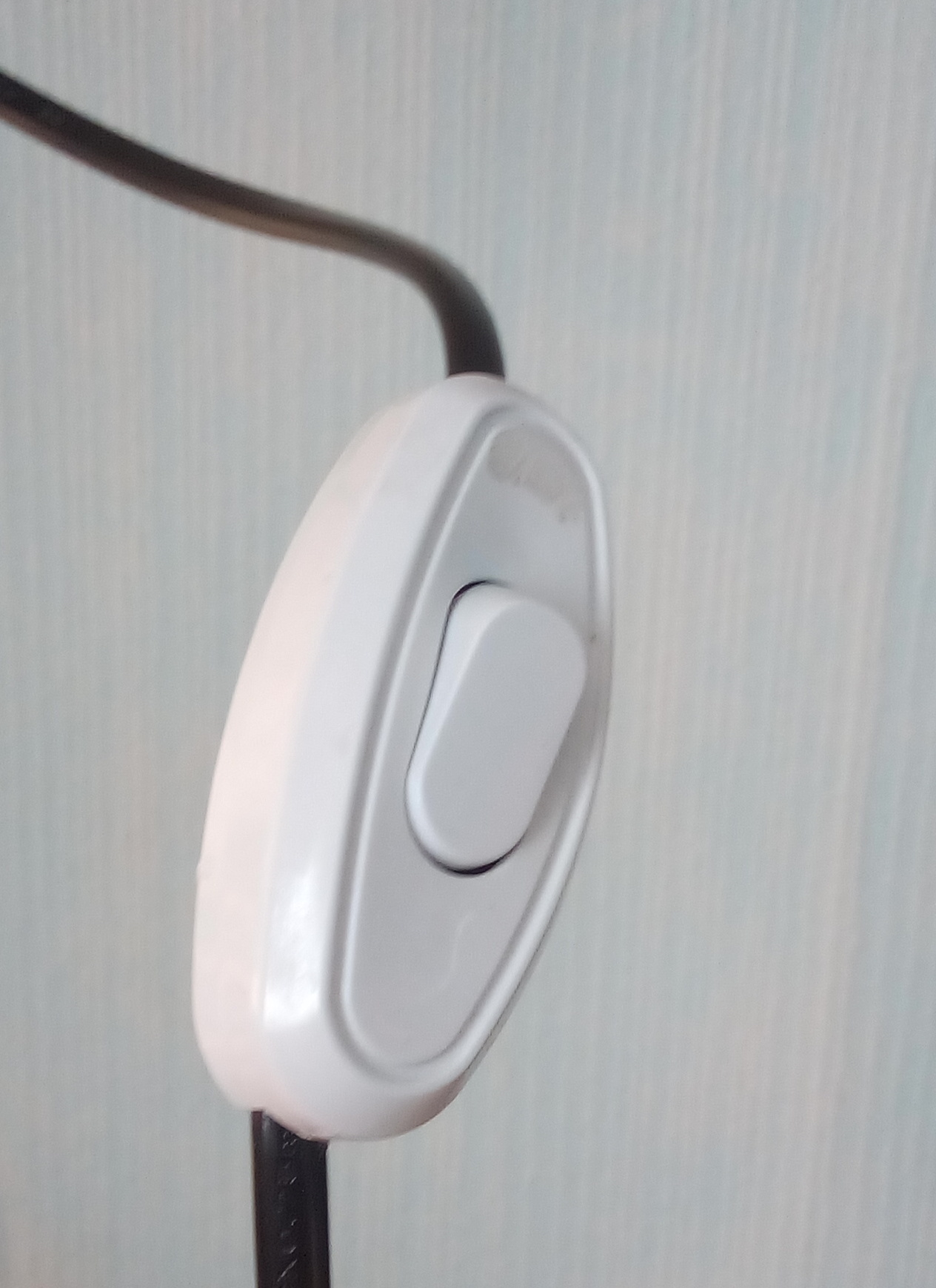 Also, the light from the lamp fell mainly on the sink, but I wanted to better illuminate the cooking table and stove.Objectives:
- Make the on / off light in the kitchen contactless;
- Evenly illuminate the sink, cooking table and stove;
- Save energy by replacing incandescent bulbs with LEDs.
He assembled the lamp 1. It consisted of a 2-meter aluminum box with a diffuser for RGB tape and a control unit. A box and a diffuser were bought ready-made at the store, there was a tape, and the control unit had long been in the corner and was waiting in the wings.The case was industrial (dustproof, waterproof). Since the tape is 12 volts, the power supply unit from 220 V to 12 V is located in the unit, the galvanic isolation board for controlling the tape based on TLP250 (optocoupler) also controlled all this arduino in a compact design.I got the galvanic isolation from the old project. Once I made a backlight for a minibar in my nightstand. When the door was opened, the touch pad recorded a change in capacity and turned on softly shimmering light. That is, the board was well suited for the current project, all that remained was to cut off everything unnecessary. There was a 5-volt linear converter on the board, it was powered by ZUNo.It was planned to turn on the lamp with a hand tray to the ultrasonic distance meter. He mounted it in the lid, and all the other parts got into the box. All "reliably" fixed with hot-melt adhesive. At the time of testing, I made a nearby button to supply power to the control unit from a light switch for external installation.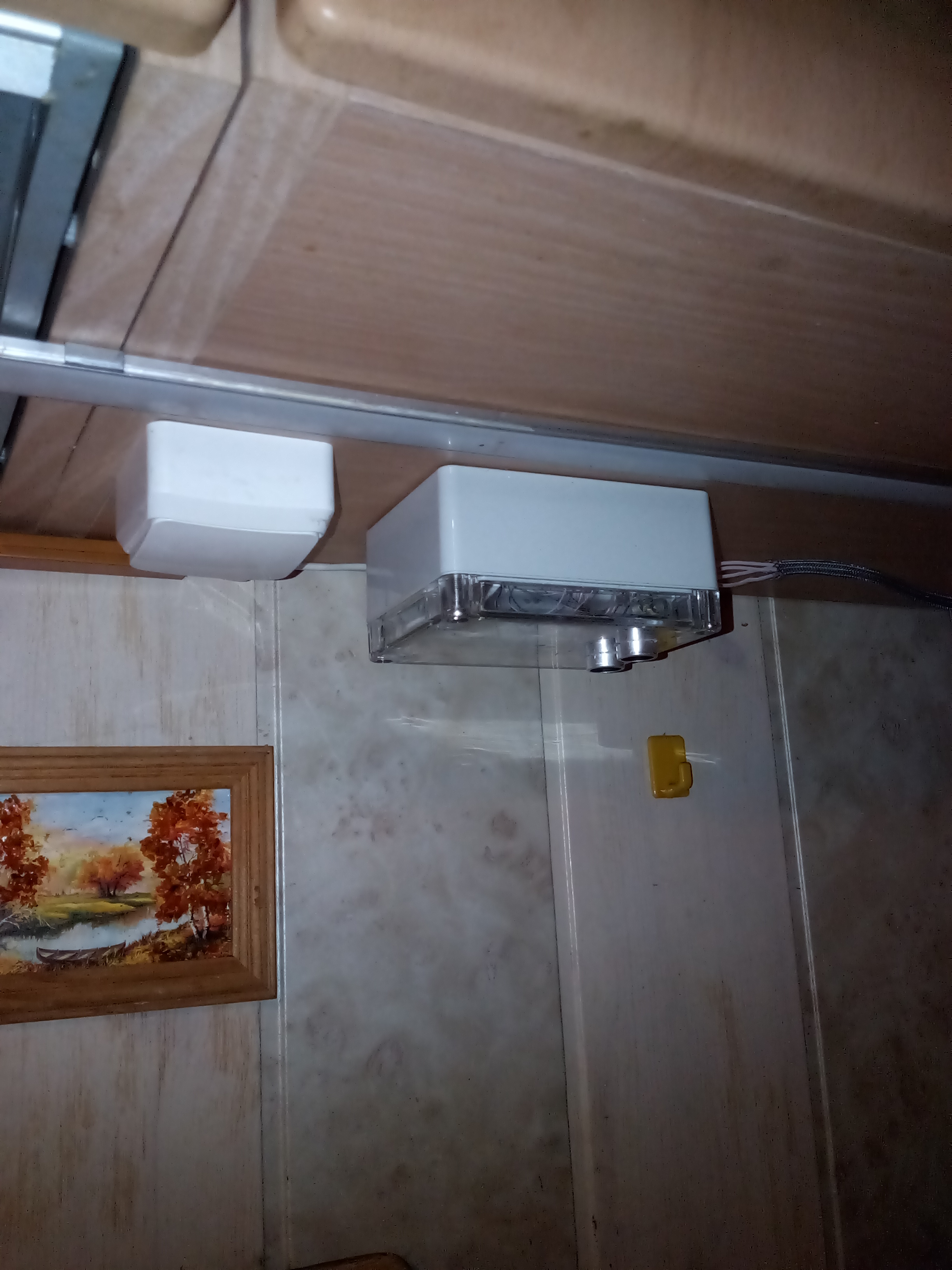 Turning on the lights has become more convenient and safer. It was attached upside down to the bottom of the kitchen cabinet and it was harder to get water from wet hands from inside.
Conclusions from the previous control unit
Lighting of the working area of the kitchen became more even and pleasant, due to the unnatural color rendering of my LED strip, the color of some products changed. For example: carrots seemed much more appetizing due to the brighter color. But it didn’t interfere much, and I hope it didn’t do much harm.With contactless on / off, everything turned out to be worse. It worked. But after 5 minutes in the off state, flashes began on the LED strip. I did not begin to redo the circuit on optocouplers and left everything as it is. Only to turn on and off began to use the new switch. Everyone liked its location and shape.Over two years of use, fat and other compounds secreted during cooking accumulated on the body and inside it. This plaque partially penetrated into the housing through the holes for the entry of wires. But due to the glossy surface of the body, this substance condenses into a gelatinous mass. It’s pleasant to the touch, odorless and ... (I didn’t taste it). I took some photos of the spot in the form of a dragon germ.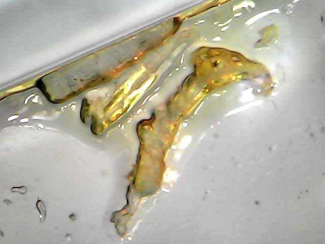
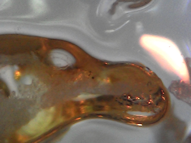 On the walls, this substance turns into a terrible raid, which is not just laundered.
What has become
Having rummaged in bins I found an unfinished expansion module for ZUNo. ZUNo is an arduino-like board for designing your own device compatible with the Z-Wave smart home. It is programmed from the environment of arduino.Manufacturer Specifications:- 28 kB Flash memory for your sketches
- 2 kB RAM available
- Z-Wave RF transmitter at 9.6/40/100 kbps
- 26 GPIO (overlaps with special hardware controllers)
- 4 ADC
- 5 PWM
- 2 UART
- 1 USB (serial port)
- 16 kB EEPROM
- 1 SPI (master or slave)
- 4 IR controllers, 1 IR learn capability
- 1 TRIAC/ZEROX to control dimmer
- 3 Interrupts
- 1 Timer 4 MHz
- I2C (software)
- 1-Wire (software)
- 8x6 Keypad Scanner (software)
- 2 service LED, 1 service button
- 1 user test LED
The expansion module makes ZUNo a full-fledged debug board, which, after debugging the prototype, can be used as a complete device.Some information from the manufacturer:- One 0-10 V analog output — control industrial dimmers
- Up to four PWM or switch outputs (up to 5 A per channel) — control contactors, switches, halogen bulbs or LED strips
- Up to eight digital 0/3 V inputs or outputs — connect various low voltage digital senors and actors
- Up to four digital 0/3, 0/5 or 0/12 V digital or analog inputs — connect industrial 10 V sensors or any Arduino-compatible sensor
- RS485 or UART — for industial meters
- OneWire — for DS18B20 or other sensors
For my project, I need 3 powerful transistors for switching 12 volts to an LED strip and a converter from 12 volts to 5 volts to power ZUNo. The rest of the periphery of the expansion module is not soldered or tested.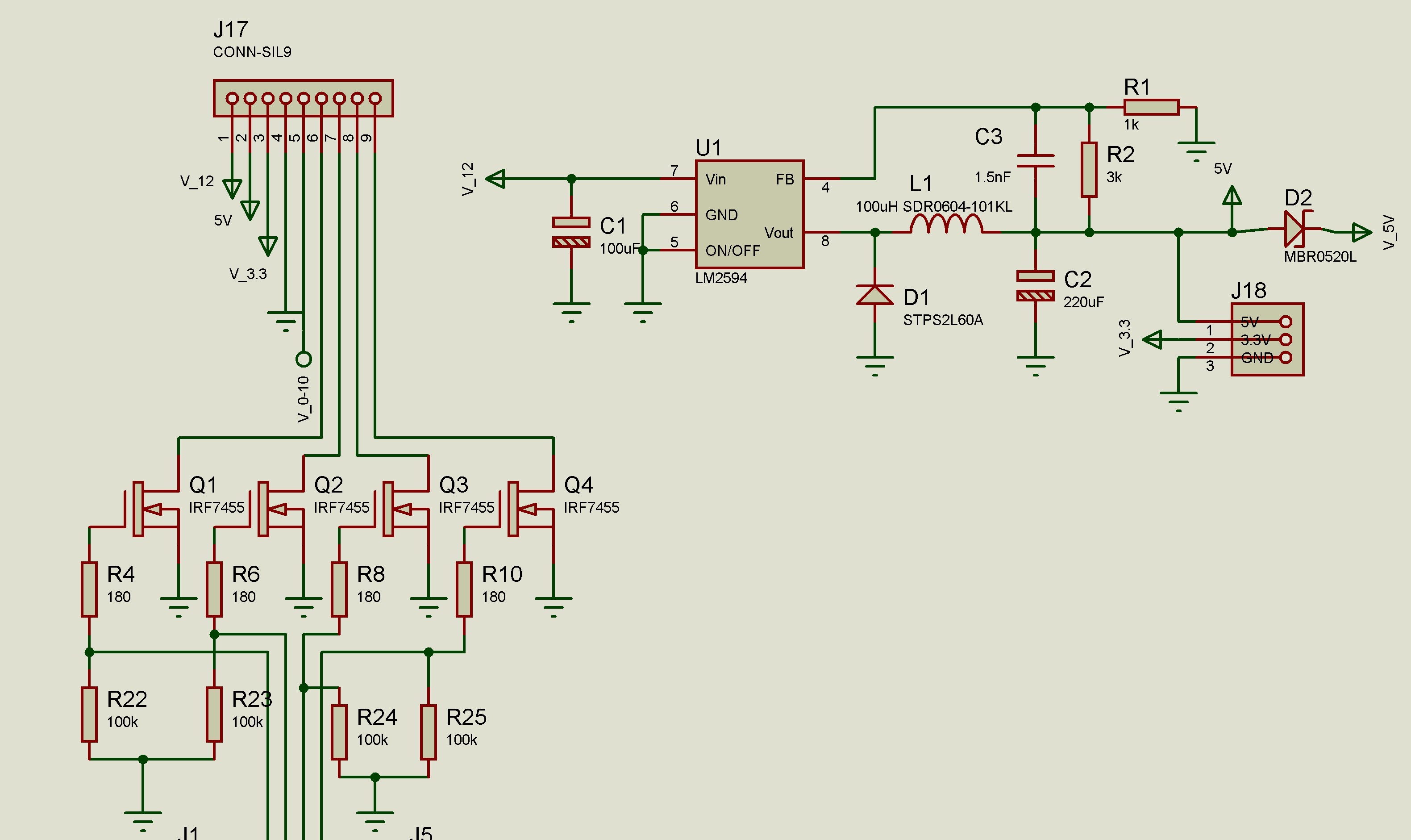 In this part of the circuit, there is not enough diode for power supply, for protection against "polarity reversal", and resistors on the gates of power field-effect transistors had to be connected to the gate, and not in front of the limiting resistor. I will write more about this in the conclusions.This expansion module is supplied in a housing from Gainta. My previous control unit was also in the case from this company, but of a different size. Unfortunately, the fastenings on the module did not fit the old case, and I did not want to drill a new one, I left the old case. The board was "planted" on hot melt adhesive.
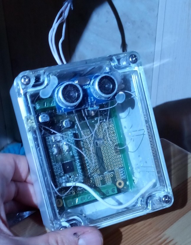
A bit about programming Arduino and ZUNo
Z-wave devices must have a certain number of classes. Classes describe device functions and interaction interfaces. For example, my lamp controls an LED strip consisting of three colors (red, green, blue). These functions are performed by the Switch multilevel class. If we add it to the sketch, we can remotely change the brightness of one of the colors. To control three colors, you need to make three instances of this class. I will not talk about this in more detail and detail. Because routine class manipulation is hidden for ZUNo users by the notion of “channel”. For example, I need three classes of Switch multilevel, so in the code should appear 3 channels of Switch multilevel and several callback functions for radio control. How to do this? You also need to add the Switch basic class,to turn the lamp on and off at the touch of a button (from the network controller interface), and not to configure 3 channels each time.You need to go to the developers website, where examples of z-uno.z-wave.me/Reference/ZUNO_SWITCH_MULTILEVEL are laid out . Each class supported by ZUNo has a description and an example. Next, copy and paste the proposed functions into your sketch. Now in the sketch there are three switch multilevel channels and 6 callback functions for responding to commands on the radio. I'm not very sophisticated in Z-Wave classes, so my previous LED strip device worked with this set of classes.The channels were declared like this:Spoiler headingZUNO_SETUP_CHANNELS(
ZUNO_SWITCH_MULTILEVEL(getRed, setRed),
ZUNO_SWITCH_MULTILEVEL(getGreen, setGreen),
ZUNO_SWITCH_MULTILEVEL(getBlue, setBlue),
ZUNO_SWITCH_BINARY(switch_getter, switch_setter)
);
This led to the generation of the following widgets in the controller after adding to the network: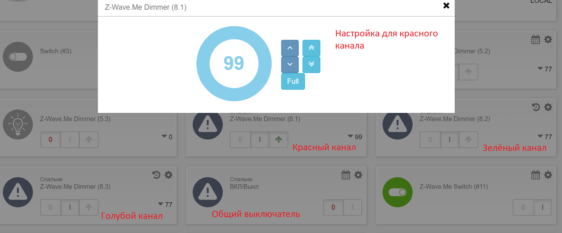 To adjust the color, it was necessary to open and configure each color in the controller menu separately. It is not convenient and slow. However, I was lucky. It turned out I'm not alone. They thought about us and made the channel z-uno.z-wave.me/Reference/ZUNO_SWITCH_COLOR . Now there is only one channel and two callback functions in the sketch. In the controller’s menu, the color setting is performed separately for each color, as well as for all at once, by selecting from the palette.
ZUNO_SETUP_CHANNELS(ZUNO_SWITCH_COLOR(SWITCH_COLOR_FLAGS_RED|SWITCH_COLOR_FLAGS_GREEN|SWITCH_COLOR_FLAGS_BLUE, getterFunction, setterFunction));
And in the controller menu it looks like this: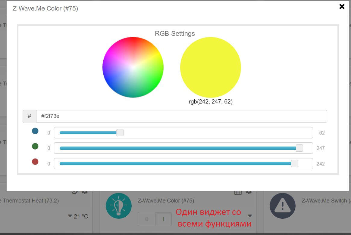 The next function responds to requests via radio. A request to read the status of one of the color channels may come.
BYTE getterFunction(BYTE component) {
  switch(component)
  {
    case SWITCH_COLOR_COMPONENT_RED:
      return pwmR;
      break;
    case SWITCH_COLOR_COMPONENT_GREEN:
      return pwmG;
      break;
    case SWITCH_COLOR_COMPONENT_BLUE:
      return pwmB;
      break;
  }
  return 3;
}
And this is a function for setting colors from the controller interface.void setterFunction(BYTE component, BYTE newValue)
{
switch(component)
{
case SWITCH_COLOR_COMPONENT_RED:
pwmR = newValue;
break;
case SWITCH_COLOR_COMPONENT_GREEN:
pwmG = newValue;
break;
case SWITCH_COLOR_COMPONENT_BLUE:
pwmB = newValue;
break;
}
radio_action = 1;
}
That's all the code you need to add to turn an arduino sketch into a sketch for ZUNo.Conclusion
After assembly and installation, all declared tasks were completed. However, the habit of turning on the light with the switch remained (it turned out to be very convenient). Contactless inclusion option also works. Among the shortcomings, I want to note the flickering of the LED lamp for a second after applying power to the control unit. This is due to the long initialization of the ZUNo peripherals. At this point, the legs are unpredictable. I think the pull-up resistor on the gate of the transistor will correct the situation if you put it after the limiting resistor. If the initialization code adjusts the legs to the output and changes the logic levels purposefully, you can experiment with the RC filter, which will not pass short pulses. I haven’t done it yet, and maybe I won’t ever do it!findings
ZUNo and its expansion module greatly simplify “home technical creativity”. However, I consider these products to be very expensive and if I worked elsewhere and Z-Wave equipment wasn’t lying around, I would do everything on ESP8266. During development I learned a new “standard” for marking wires from the power supply.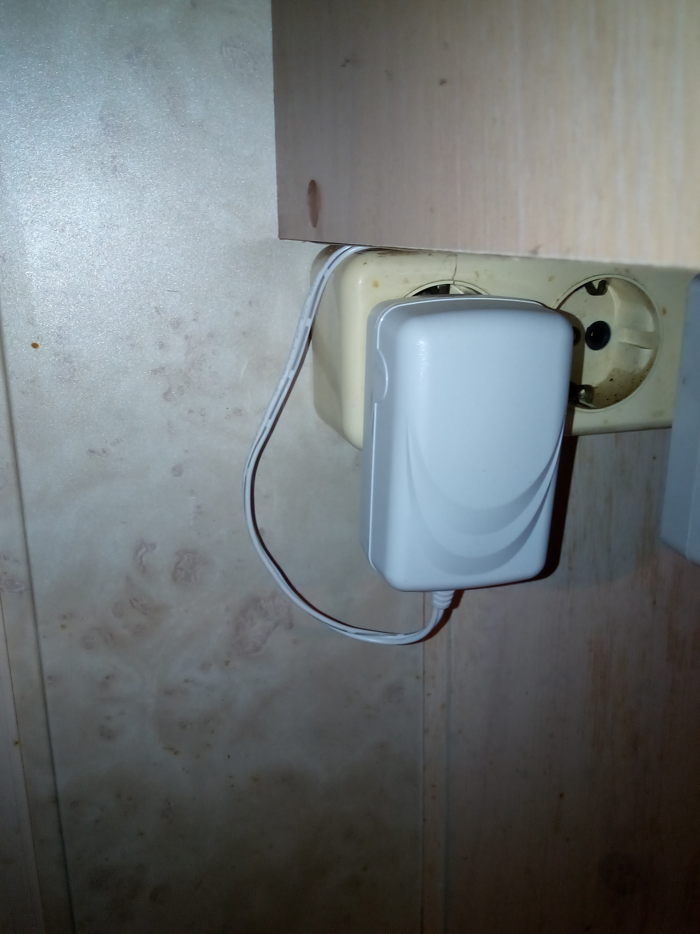 Now not only the earth is marked with a black stripe, but like in my case the “positive" wire. For the expansion module, this turned out to be important. The 5-volt LM2594 converter has failed (the price in Chip and Dip is about 200 rubles). I hope that in the next version of the expansion module there will be a protective diode against “polarity reversal”. And I will check the polarity of the supply wires. Another drawback is associated with the body. The case looks good, but I could not connect the wires without tweezers to the terminal blocks. I hope that there will be a version with other terminal blocks (for connecting wires from above, or at an angle).I do not like to store photos on cloud services and often make backups. Therefore, most of the photographs associated with the design process and the lamp 1 are irretrievably corrupted.
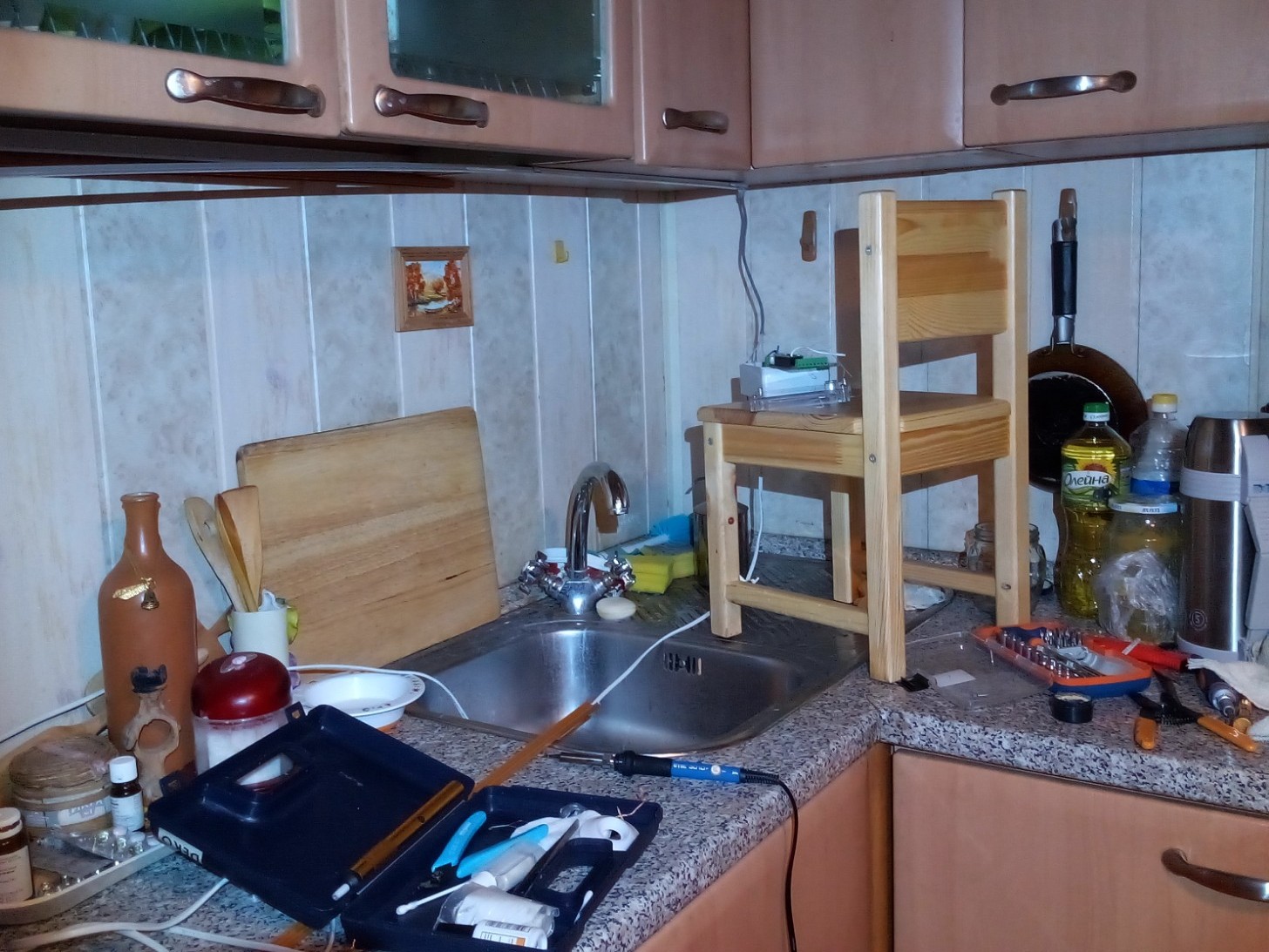
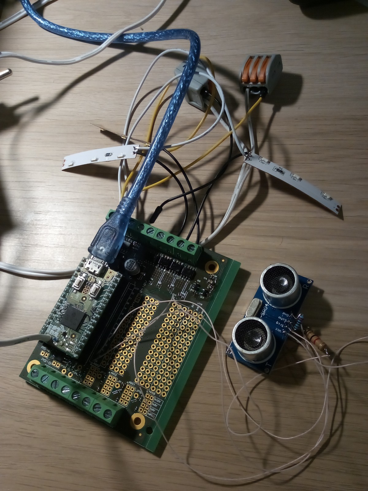 This is all that remains of the assembly and debugging process.And it looks like the backlight put into operation, if you bend a little. If you straighten, then the box and the switch is not visible.
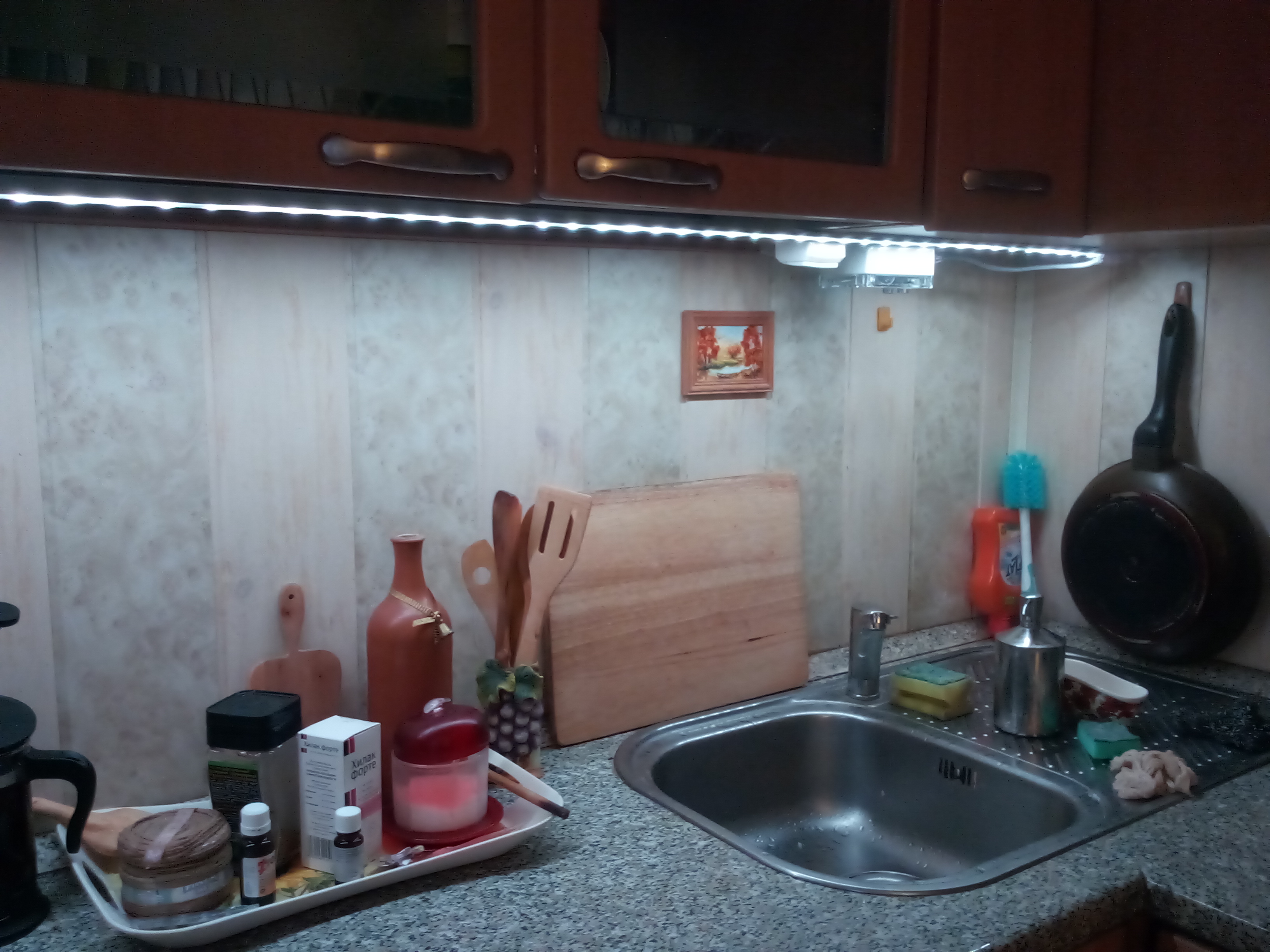
Sketch for ZUNo. I attach, only to confirm that everything is elementary#include "EEPROM.h"
#include "EEPR.h"
int readPin = 9;
int triggerPin = 10;
byte controlState = 0;
word lastValue;
#define REDPIN PWM1
#define GREENPIN PWM2
#define BLUEPIN PWM3
ZUNO_SETUP_CHANNELS(ZUNO_SWITCH_COLOR(SWITCH_COLOR_FLAGS_RED|SWITCH_COLOR_FLAGS_GREEN|SWITCH_COLOR_FLAGS_BLUE, getterFunction, setterFunction));
#define ON 1
#define OFF 0
uint8_t switch_=OFF;
uint8_t pwmR=0;
uint8_t pwmG=0;
uint8_t pwmB=0;
uint8_t b_pwmR=0;
uint8_t b_pwmG=0;
uint8_t b_pwmB=0;
enum
{
DEF_R = 255,
DEF_G = 255,
DEF_B = 255
};
uint8_t radio_action = 0;
void setup()
{
init_EEPROM();
Serial.begin();
pinMode(readPin, INPUT);
pinMode(triggerPin, OUTPUT);
digitalWrite(triggerPin, LOW);
pinMode(REDPIN, OUTPUT);
pinMode(GREENPIN, OUTPUT);
pinMode(BLUEPIN, OUTPUT);
analogWrite(REDPIN, pwmR & 0xff);
analogWrite(GREENPIN, pwmG & 0xff);
analogWrite(BLUEPIN, pwmB & 0xff);
}
int act=1;
int actf = 0;
int cnt=57;
void loop()
{
int tmp;
digitalWrite(triggerPin, LOW);
delayMicroseconds(10);
digitalWrite(triggerPin, HIGH);
delayMicroseconds(10);
digitalWrite(triggerPin, LOW);
tmp = pulseIn(readPin, HIGH, 100000);
lastValue = tmp / 58;
Serial.print(" cm= ");
Serial.println(lastValue);
if (lastValue < 30)
{
cnt++;
}
else
{
cnt--;
}
if (cnt > 55)
{
act=1;
}
if (cnt > 60)
cnt= 60;
if (cnt < 50)
{
act=0;
actf=0;
}
if (cnt < 45 )
cnt = 45;
if ((act == 1) && (actf == 0))
{
actf = 1;
if (switch_ == OFF)
{
switch_=ON;
b_pwmG = pwmG;
b_pwmB = pwmB;
b_pwmR = pwmR;
}
else
{
switch_=OFF;
b_pwmR=0;
b_pwmG=0;
b_pwmB=0;
}
analogWrite(REDPIN, b_pwmR & 0xff);
analogWrite(GREENPIN, b_pwmG & 0xff);
analogWrite(BLUEPIN, b_pwmB & 0xff);
}
Serial.print("cnt = ");
Serial.print(cnt);
Serial.print(" || ");
Serial.print(pwmR);
Serial.print(" ");
Serial.print(pwmG);
Serial.print(" ");
Serial.print(pwmB);
Serial.print(" ");
Serial.println("");
if(radio_action)
{
radio_action = 0;
eepr_save_col();
analogWrite(REDPIN, pwmR & 0xff);
analogWrite(GREENPIN, pwmG & 0xff);
analogWrite(BLUEPIN, pwmB & 0xff);
}
}
BYTE getterFunction(BYTE component) {
switch(component)
{
case SWITCH_COLOR_COMPONENT_RED:
return pwmR;
break;
case SWITCH_COLOR_COMPONENT_GREEN:
return pwmG;
break;
case SWITCH_COLOR_COMPONENT_BLUE:
return pwmB;
break;
}
return 3;
}
void setterFunction(BYTE component, BYTE newValue)
{
  switch(component)
  {
    case SWITCH_COLOR_COMPONENT_RED:
      pwmR = newValue;
      break;
    case SWITCH_COLOR_COMPONENT_GREEN:
      pwmG = newValue;
      break;
    case SWITCH_COLOR_COMPONENT_BLUE:
      pwmB = newValue;
      break;
  }
  radio_action = 1;
}