Probably, the time of religious wars of AVR against STM has already passed, but no, no, yes, there are outbreaks of clashes between the two camps. Almost any publication on AVR crafts will definitely have a comment like “Yes, how much you can shag your grandmother, it’s high time to switch to STM”, then the variations on the subject of price, number of legs and timers. If the STMshcher is more advanced, there will certainly be an indication that there is no DMA in the AVR and will not, therefore the AVR should die. Why a simple blink-voltmeter-thermometer DMA, a mountain of 16 bit timers, 100 legs and a 12 bit ADC, no one usually explains. Why do we need such a harvester in a device that Tiny13 can easily take out, which at the same time is not loaded even on a third of its resources, no one will understand. You just have to switch to STM32, and that's it. For here.And I must say, people have a craving for novelty. But really, can I try? What if you like it? Here are just the Reference Manual for the popular STM32F103C8T6, on which the most massive 1126-page Blue tablet is based, somehow it doesn’t really have a “quick start”. Even a separate utility, so hated by the elders “kalokub”, and that must be studied, what's what. Yes, and having delved into Cube, it is unlikely to start in 5 minutes, the footcloth generated by him is not the most accessible reading matter for the night, it’s just to get into the forehead, which not everyone can talk about there.Numerous articles, similar to this one, about quick and easy start in STM deserve a separate discussion. For all such articles, at first I was very confused by one circumstance. Nowhere is there a detailed explanation of what we are actually writing here. A bunch of screenshots of how to create a project, then immediately a wall of code, do it like this! And what is there, why is it, why is it so, where to get all these seemingly understandable words from, no one delves into it, because the forces ran out when writing a manual on installing Cale and Cuba, and on launching the project. Only after some time, individual for each, does the understanding of what is happening and why come. In turn, I propose a way to start not from the beginning, like everyone else, but from the end. Now we will do the opposite, do not configure the controller, write code and debut it, but immediately proceed to the debug,and record our actions in the form of code.So, we install Keil as a free (up to 32KB code) environment. We will not describe this action, this is on the Internet, and the installer’s step-by-step must be mastered by the person who goes to STM. We start the project: Project-New uVision Project, create a folder and a project file. The controller selection window opens, enter 103C8 into the search and agree on the only selected model.Next, we get to the library selection window: Here we put three daws: CMSIS-CORE, Device-Startup and Device-GPIO. This set is quite enough to bounce a leg, lighting the LED. Then you still have to configure, you can’t get anywhere from this. Alt + F7 launches the settings window located Project-Options for Target, where on the “Output” tab you need to check the “Create HEX-File” checkbox to create a firmware file that we will upload to the controller. Next, in the “Debug” tab, we select ST-Link, which, in fact, will load the firmware and debut:
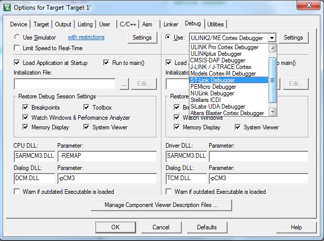 By the “Setting” button next to the programmer’s selection window, we get to the “Cortex-M Target Driver Setup” window, where in the “ Flash Download "put a daw" Reset and Run ".In the project tree, right-click on the “Source Group 1” folder, in the wizard that opens, create the main.c file, in which we will soon write the code. In the opened main.c, right-click on the first and most important inclusion:
 Add the code consisting of main and endless while:
#include "stm32f10x.h"                  // Device header
int main(){
	while(1){
	}
}
Oddly enough, this is all for now, this is a ready-made and understandable program that correctly compiles and loads into the controller. We press F7 and we see that the firmware has been successfully assembled, there are no errors or warings.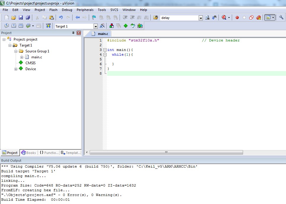 From this moment on, the controller is fully accessible to us, we can enter it under the debug line and twist-twist it in all directions, and it will respond.The Ctrl + F5 keys lead us into debug, and the “System Viewer Windows” button allows you to launch the windows for controlling the register registers and controlling the legs of the GPIO.
 Further, I suggest that you still use the Reference Manual, especially since you do not even need to download it, it is available by clicking in the “Books” tab of the “View” menu:
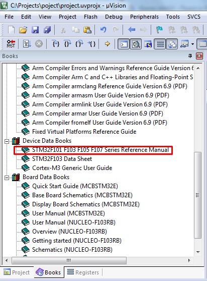 Now I propose to use the following reasoning. From the pinout on the Blue Tablet, it can be seen that the LED hangs on the leg of port 13. Numerous Internet resources and discussions always mention that before you do something in STM, you need to enable something, otherwise, set the clock. Without further ado, we write in the search box of the pdf reader what we need, namely, enable port C: “PORT C CLOCK ENABLE”. We
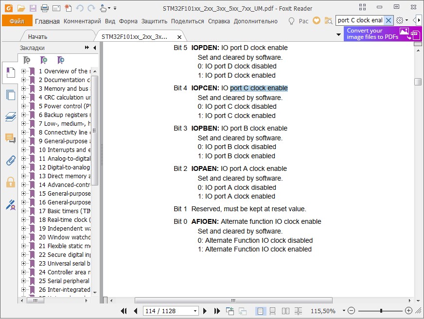 get into the following picture: From this we can conclude that the clocking of port C is enabled in the IOPCEN register. With this knowledge, we go to the RCC tab in debug mode, and enter this name in the search bar:
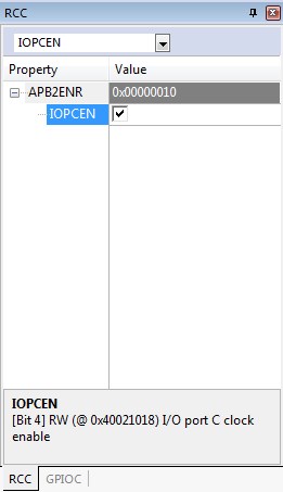 Mark the required checkbox with a checkmark, and from this moment we consider port C enabled.Now, remembering the long-suffering AVR, we will look for the setting of the actual pin. In order for it to work, it is necessary to explain what exactly we want from it. And we want to jump with foot number 13 of port C, for this we need to set the mode of its operation. In the search bar in the Referense Manual we drive in “Port bit configuration”, which expresses our desire to read where the leg settings are hidden. The search leads us to a table from which it follows that in order to assign a leg as an output, it is necessary to configure the MODE and CNF registers:
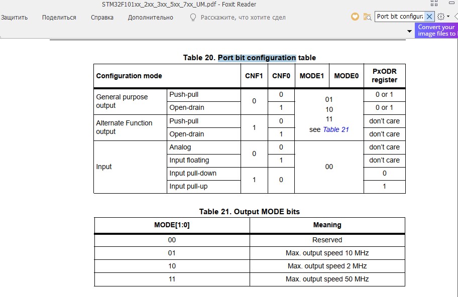 From table No. 20 it is clear that for assigning a leg as a Push-Pull output, it is necessary to reset the registers CNF0 and CNF1, and the pair state MODE0 and MODE1 are described in table No. 21, I will choose the upper option, up to 10MHz, MODE0 = 1, MODE1 = 0. This is what I will do in the GPIOC window for the registers CNF13 and MODE13
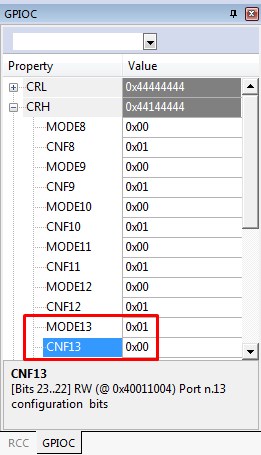 Now we have configured the clock and mode of operation of the port. It's time to find out exactly how to jump a leg. In English, set the port bit is written as “Port bit set”, and we will look for this phrase in the manual:
 Search leads us to a page with a table, which clearly shows that the BSRR register, consisting of BS and BR pairs, is responsible for setting the status of the port leg , Bit set and Bit reset, respectively. We find these registers in the GPIOC window in debug mode and enjoy the control of leg number 13 directly by poking jackdaws with the mouse into the corresponding checkboxes:
 An LED on the blue pill board hangs between the leg and the VCC, therefore controlling it back to the register name. The Bit Set (BS13 register) extinguishes it, and the Bit Reset (BR13 register) ignites it. These are registers of atomic operations, they are reset after setting the checkbox. It is possible to control the foot through the ODR register (clause 9.2.4 Port output data register (GPIOx_ODR) in the reference manual), it clearly shows what the installation and resetting of the jackdaw leads to.
 A green and dimming green LED indicates that everything is working correctly. It remains only to write all this in the form of code in the main.c. This is where the very raisins appear, which distinguishes this method of comprehending the STM controller through debug from the others that the entire Internet is littered with. I suggest just rewriting what we see in the debug window into code. Example:
 Set the port operation mode and enable clocking;
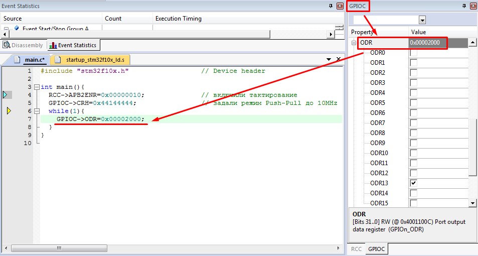 They turned on the port leg, waited, turned it off, and so on:
#include "stm32f10x.h"                  // Device header

int main(){
	RCC->APB2ENR=0x00000010;			//
	GPIOC->CRH=0x44144444;			//   Push-Pull  10MHz
	int i;								//     /
	while(1){
		GPIOC->ODR=0x00002000;		//  LED,
		i=2000000;					//
		while (i) i--;					//
		GPIOC->ODR=0x00000000;		//  LED
		i=2000000;					//
		while (i) i--;
	}
}
Of course, this method is far from the best and not correct, but in my opinion the most understandable and simple. In addition, he introduces to working with a datasheet (reference manual) and does not scare away, like reading mana and writing multi-page footcloths of code for Blink. Yes, there are no layers of abstractions, much has been missed, but I think you can forgive this for the elementary start. Reading mana and correct work with registers is then, now we have a blinking LED and we basically understand how and what we did, and most importantly, where all these abbreviations came from. If I had been shown this way of studying STM before, perhaps I would not have collected over 9000 different programmers for AVR in which there was no debug, but would have taken up on the Cortex right away. Indeed, in AVR there is no intelligible and accessible debug, but anyway, it's too early to forget Tiny13. She takes out her tasks.