Assembling a portable magnetometer
Translation of an article from the Instructables training materials site A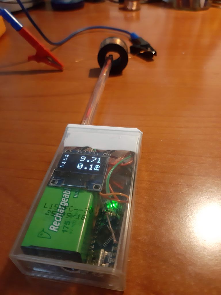 magnetometer , sometimes also called a gaussometer, measures the strength of a magnetic field [ in this case, magnetic induction / approx. perev. ]. This is a device necessary for measuring the strength of permanent magnets and electromagnets, as well as for establishing the field shape of non-trivial combinations of magnets. It is sensitive enough to detect the magnetization of metal objects. If the probe works fast enough, it will be able to detect time-varying fields from motors and transformers.Mobile phones usually have a three-axis magnetometer, but it is optimized for a weak magnetic field of the Earth with a force of 1 Gauss = 0.1 mT [ millilitles] and is saturated in fields with induction of several mT. It is usually not clear where exactly this sensor is located in the telephone, and it is often impossible to place it inside a bottleneck such as a magnet cut. Moreover, it is better not to bring the smartphone to strong magnets at all.In this article I will describe how to make the simplest portable magnetometer from common components: we need a linear Hall sensor, Arduino, a display and a button. The total cost of the device does not exceed € 5, and it will measure induction from -100 to +100 mT with an error of 0.01 mT - much better than you might expect. To obtain accurate absolute indicators, you will need to calibrate it: I will describe how this is done with the help of a long home-made solenoid.
Step 1: Hall Sensor
The Hall effect is often used to measure magnetic fields. When electrons pass through a conductor placed in a magnetic field, they are carried to the side, as a result of which a transverse potential difference appears in the conductor. By choosing the material and geometry of the semiconductor correctly, you can get a measurable signal, which can then be amplified and produce a measurement of one component of the magnetic field.I use SS49E as it is cheap and affordable. What is worth noting from its documentation :- Power: 2.7 - 6.5 V, which is perfectly compatible with 5 V for Arduino.
- Zero signal: 2.25-2.75 V, approximately halfway between 0 and 5 V.
- Sensitivity: 1.0-1.75 mV / G, so calibration will be required to get accurate results.
- Output voltage: 1.0 - 4.0 V (for operation from 5 V): the range is covered by the Arduino ADC.
- Range: minimum ± 650 Gs, usually + / 1 1000 Gs.
- Response time: 3 μs, that is, it is possible to carry out measurements with a frequency of tens of kHz.
- Operating current: 6-10 mA, enough for a battery.
- Temperature error: 0.1% per degree Celsius. It seems a little, but a deviation of 0.1% gives an error of 3 mT.
The sensor is compact, 4x3x3 mm, and measures the component of the magnetic field perpendicular to its front side. It gives a positive value for fields going from the back to the front - for example, when it faces the south pole of a magnet. The sensor has three contacts, +5 V, 0 V and the output is from left to right when viewed from the face.Step 2: Required Materials
- Linear Hall Effect Sensor SS49E. € 1 for 10 pieces.
- Arduino Uno with prototyping board or Arduino Nano without pins for the portable version.
- Monochrome OLED display SSD1306 0.96 ”with I2C interface.
- Button.
For probe:- Ballpoint pen or other durable tube.
- 3 thin wires slightly longer than the tube.
- 12 cm heat shrink with a diameter of 1.5 mm.
For portable version:- A large Tic-Tac box (18x46x83) or something similar.
- 9V battery contacts
- Switch.
Step 3: First Version - Using the Prototyping Board
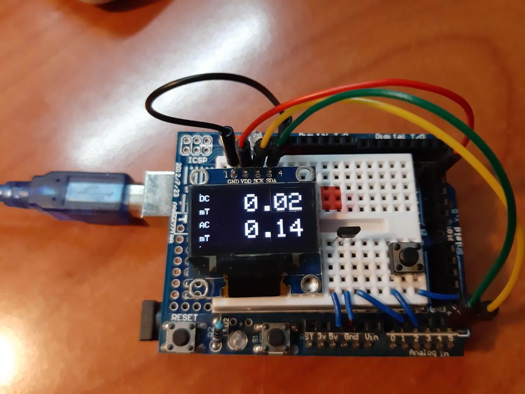
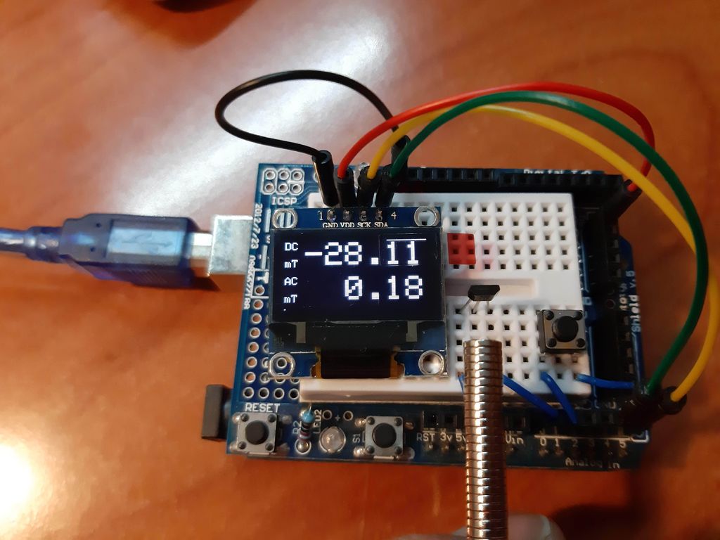 First, always build a prototype to test the operation of all components and software! The connection is visible in the picture: the Hall sensor is connected to the contacts Arduino + 5V, GND, A1 (from left to right). The display connects to GND, + 5V, A5, A4 (from left to right). The button, when pressed, should close the ground and A0.Code written in Arduino IDE v. 1.8.10. Requires installation of the Adafruit_SSD1306 and Adafruit_GFX libraries.If everything is done correctly, the display should give DC and AC values.
Step 4: A bit about code
If you are not interested in the code, you can skip this part.A key feature of the code is that the magnetic field is measured 2,000 times in a row. It takes 0.2 - 0.3 seconds. By tracking the sum and square of the sum of the measurements, it is possible to calculate the mean and standard deviations, which are given out as DC and AC. Averaging over a large number of measurements, we increase the accuracy, theoretically, by √2000 ≈ 45. It turns out that using a 10-bit ADC, we get the accuracy of a 15-bit ADC! And it matters: 1 step of the ADC is 4 mV, that is, ~ 0.3 mT. Due to averaging, we reduce the error from 0.3 mT to 0.01 mT.As a bonus, we get the standard deviation, thus determining the changing field. A field oscillating with a frequency of 50 Hz goes through about 10 cycles during the measurement, so you can measure the value of AC.After compilation, I got the following statistics: Sketch uses 16852 bytes (54%) of program storage space. Maximum is 30720 bytes. Global variables use 352 bytes (17%) of dynamic memory, leaving 1696 bytes for local variables. Maximum is 2048 bytes.Most of the space is occupied by Adafruit libraries, but there is still plenty of room to add functionality.Step 5: Cooking the Probe
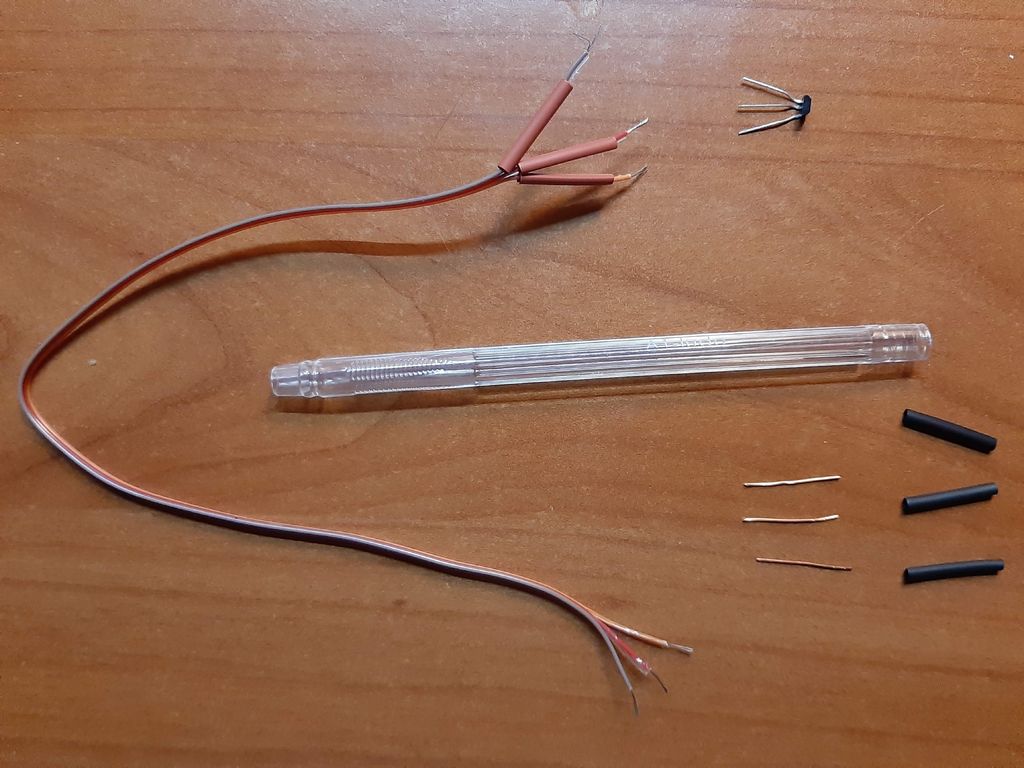
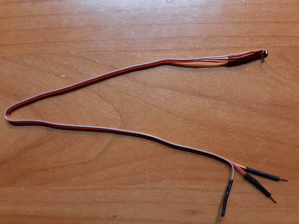 The probe is best fixed at the end of a narrow tube: it will simply be placed and held in tight places. Any tube made of non-magnetic material will do. The old ballpoint pen was perfect for me.Prepare three thin flexible wires slightly longer than the tube. In my cable there is no logic in the colors of the wires (orange + 5 V, red 0 V, gray - signal), it's just easier for me to remember them.To use a probe with a prototype, solder pieces of wire to the end of the cable and insulate them with heat shrink. Later they can be cut off and soldered directly to the Arduino.
Step 6: Assembling the Portable Instrument
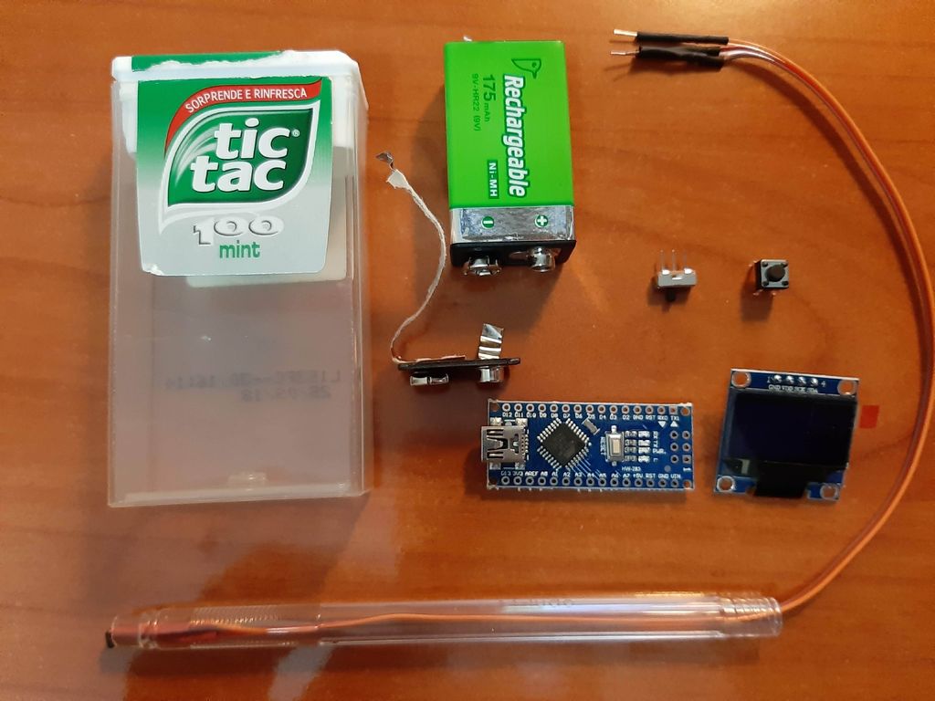 The 9V battery, OLED screen and Arduino Nano comfortably fit inside a large Tic-Tac box. Its advantage is transparency - the screen is easy to read, even when inside. All fixed components (probe, switch and button) are placed on the cover so that everything can be removed from the box to replace the battery or update the code.I never liked 9V batteries - they have a high price and low capacity. But in my supermarket, they suddenly started selling their rechargeable version of NiMH for € 1, and I found that they were easy to charge if I fed 11 V through a 100 Ohm resistor and left overnight. I ordered cheap battery connectors for myself, but they did not send them to me, so I disassembled the old 9 V battery to make a connector out of it. Plus 9V batteries in its compactness, and in that Arduino works well on it when connected to Vin. At +5 V there will be an adjustable voltage of 5 V, which will be needed for the OLED and the Hall sensor.The Hall sensor, screen and button are connected in the same way as on the prototype. Only the power button is added, between the battery and the Arduino.
Step 7: Calibration
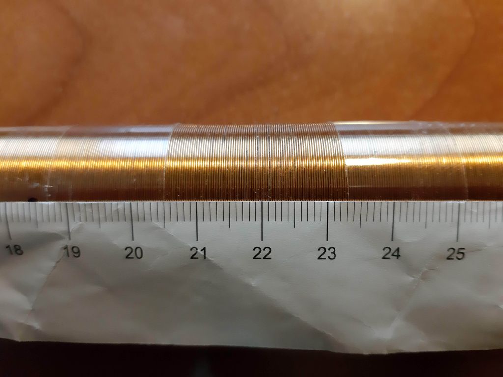
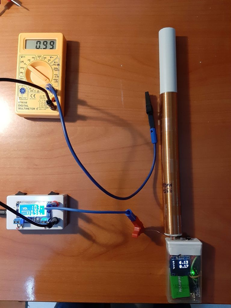
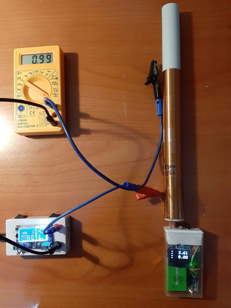 The calibration constant in the code corresponds to the number prescribed in the documentation (1.4 mV / G), however, the range of this value (1.0-1.75 mV / G) is allowed in the documentation. To get accurate results, you need to calibrate the probe.The easiest way to get a well-defined magnetic field is to use a solenoid. The magnetic induction of the solenoid field is B = μ 0 * n * I. The magnetic constant (or magnetic permeability of the vacuum) is a natural constant: μ 0 = 1.2566 x 10 -6T / m / A. The field is uniform and depends only on the winding density n and current I, which can be measured with an error of about 1%. The formula works for an solenoid of infinite length, but it serves as a very good approximation for the field in its center if the ratio of its length to diameter exceeds 10.To assemble a suitable solenoid, take a hollow cylindrical pipe 10 times longer than the diameter and wind it from an insulated wires. I used a PVC tube with an external diameter of 23 mm and made 566 turns extending 20.2 cm, which gives us n = 28 / cm = 2800 / m. The wire length is 42 m, the resistance is 10 ohms.Apply power to the coil and measure the current with a multimeter. Use either an adjustable current source or a variable resistor to control the current. Measure the magnetic field for different current values and compare the readings.Before calibration, I received 6.04 mT / A, although in theory it should have been 3.50 mT / A. Therefore, I multiplied the calibration constant in the 18th line of the code by 0.58. Done - the magnetometer is calibrated!
 Source: https://habr.com/ru/post/undefined/
All Articles