How to design power grid protection equipment
Hi Habr. The ASCON blog is returning to its readers. Now it will have posts not only of our employees, but also guest posts of engineers working with ASCON products. The first story is about the design of equipment for the energy sector.Says Yevgeny Fofanov, head of the department of design and technological support for the production of Uralenergoservice (Yekaterinburg).What are we doing
For more than 25 years, our company has been developing and manufacturing equipment for transmitting relay protection and emergency control commands for domestic energy needs. Our products are installed at power facilities of Rosseti, Inter RAO, RusHydro, large oil and gas and metallurgical enterprises.We provide a full range of services, including design, development, delivery, configuration and commissioning, warranty and post-warranty service, equipment modernization at the installation site. In addition, licensed advanced training courses for employees of organizations operating our equipment are held in our own classroom. Source goodfon.ruThe requirements for the design of our products are standardized and determined by GOST R IEC 60297-3-101-2006, which applies to 19-inch telecommunication equipment. Therefore, the creative component in the development of shells for our products is seriously limited by the requirements of this document.
How do we launch a new product
As a rule, when developing a new product, the project team is first formed, which will deal with the solution of fundamental problems. In it, under the guidance of the chief engineer, developers, circuit designers and design engineers work. At the first stage, on the basis of the received technical specifications, a structural diagram of the product is compiled, its overall mass characteristics are determined, and the components are broken down. The designer determines the requirements for the product shell and its components, after which it determines the dimensions of the printed circuit boards installed in the blocks.After the approval of the design features of the product, the circuit designer receives a drawing of the printed circuit board template, which is planned to be installed in one of the units of the device in the future. The work is carried out in the Altium Designer program. As a result, files containing the design of the printed circuit board of the block under development are created. Then the model of the printed circuit board is exported to the * .step format, which is transmitted to the designer for subsequent verification of compliance with the requirements contained in the printed circuit board template.The designer opens the resulting file in the KOMPAS-3D system and embeds the PCB assembly into the assembly of the block under development. Then it checks the model of the resulting assembly unit for the absence of geometric intersections. When problem areas are identified together with the circuit designer, the designer finds ways to solve them, then the geometry matching process is repeated.After approval of the printed circuit board, its files are transferred to the procurement department and then sent to the manufacturers of printed circuit boards.The designer, in turn, is engaged in the preparation of the hull of the product. Mostly, components made of sheet material are used as chassis elements. To create them, the designer works in KOMPAS-3D with sheet design teams. With their help, complex operations with sheet materials are performed: construction of shells, cutting of stampings, closure of corners and, most importantly, construction of reamers. This functionality has sufficient capabilities to fulfill all our needs, reliable and easy to use.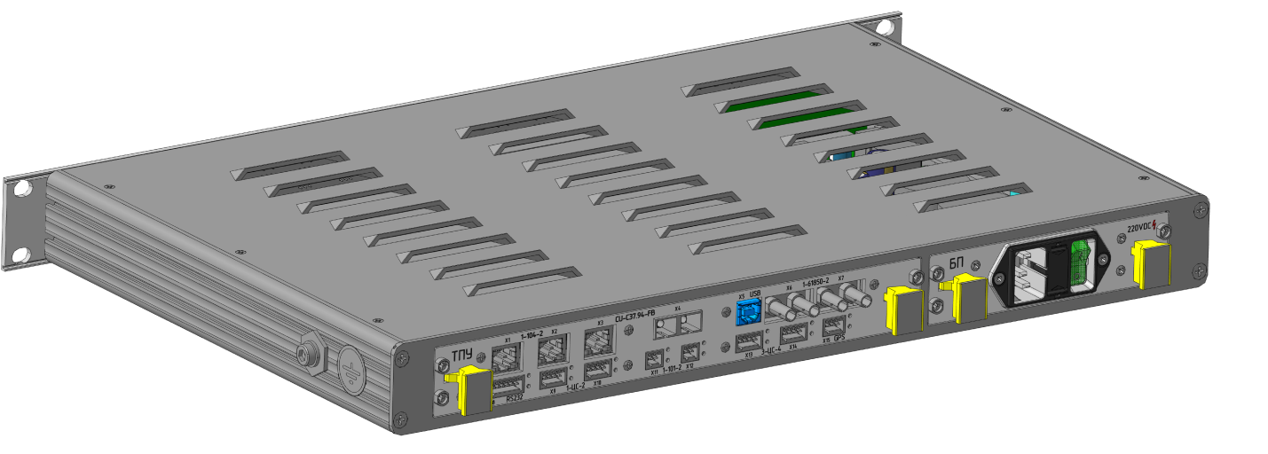 Product body made using sheet modeling commandsWithout fail, we use the Standard Products directory, which, in addition to hardware models, includes the useful subsection Structural Elements. The tool allows you to add various grooves, holes, grooves and grooves both in the 3D model of the product, and in a flat drawing. Separately, we note the presence of the section "Enterprise Products" with user data.In our case, it includes all data collected from foreign catalogs on specialized hardware (both 3D geometry and data to fill out the specification).
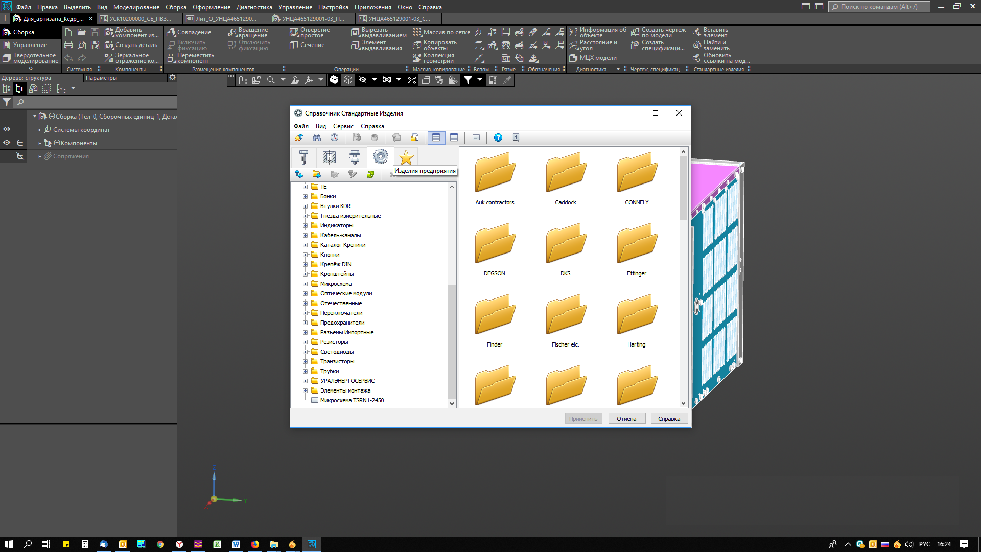 Nomenclature of products “Uralenergoservice” in the standard products directoryIt is worth mentioning the TraceParts resource, which has published more than 100 million parts from more than 800 official catalogs from many manufacturers from around the world. When downloading files from this resource (usually in * .step format), sometimes it becomes necessary to simplify the geometry of the part. Unfortunately, the imported files do not contain details in the construction tree that would allow making changes to the part. Therefore, editing the part must be preceded by the restoration of the history of construction.To restore the tree of constructions lost during the export, we use the 3D model recognition application for KOMPAS-3D. When processing complex parts, certain difficulties may arise, but the library copes with simple models quickly and without errors. As a result, we get a model file prepared for making changes to KOMPAS-3D.
Interaction with allies
After completing the construction of the housing model, it is transferred to the side, to our partners, manufacturers of housing parts. To do this, the file from KOMPAS is exported to a step-file, after which it is transferred through the file hosting service to our subcontractors involved in machining. They analyze the received file, carry out design and technological adaptation to the capabilities of their production, and then send their version of the step file for approval. An interesting point in this interaction is that we do not coordinate the drawings for the product. All approvals are part of the discussion of the 3D model. This can significantly reduce the development time of the hull of the product.After solving all technical issues, the cost of the product is agreed. At this stage, sometimes you have to make changes to the model in order to optimize costs. Then comes the delivery of the first test samples.Cable and harness routing
At the same time as preparing the production of case parts, the designer works with a 3D assembly file for the entire product. Places are determined for the optimal routing of motherboards, the necessary connectors are laid, the type of wire is determined. To do this, we use the Equipment: Cables and harnesses application. Its application allows the first time to calculate the required length of wire connections, as well as release the necessary design documentation for cables and harnesses.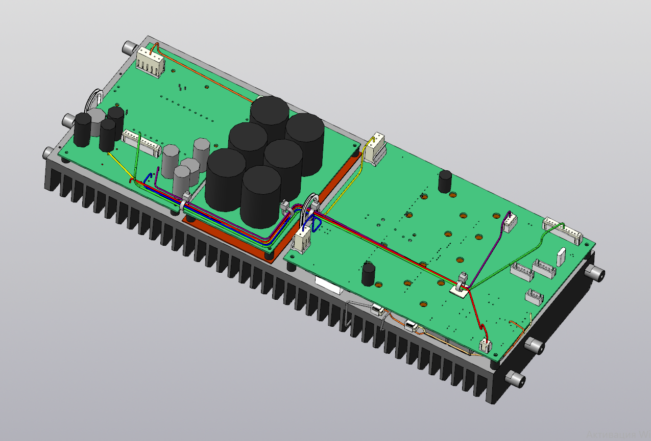 Application example: Equipment: Cables and harnessesIn justified cases, the necessary calculations are carried out using CAE systems, for example, thermal simulation of the operation of the most powerful units of the device. After that, the calculation results are studied and a decision is made on making changes to the structural elements. These virtual tests can be successfully performed using the FlowVision system (developed by TESIS). But, since now there is no constant need for such calculations, it is economically more profitable to perform such work one-time, on a contractual basis, with the help of our contractors.
Visualization: showing the future product
After a detailed drawing of the appearance of the product, it is time to prepare high-quality images of the new device - for advertising booklets, catalogs and other printing products. Here we use Artisan Rendering for KOMPAS-3D, which turns multi-color 3D models into realistic product images.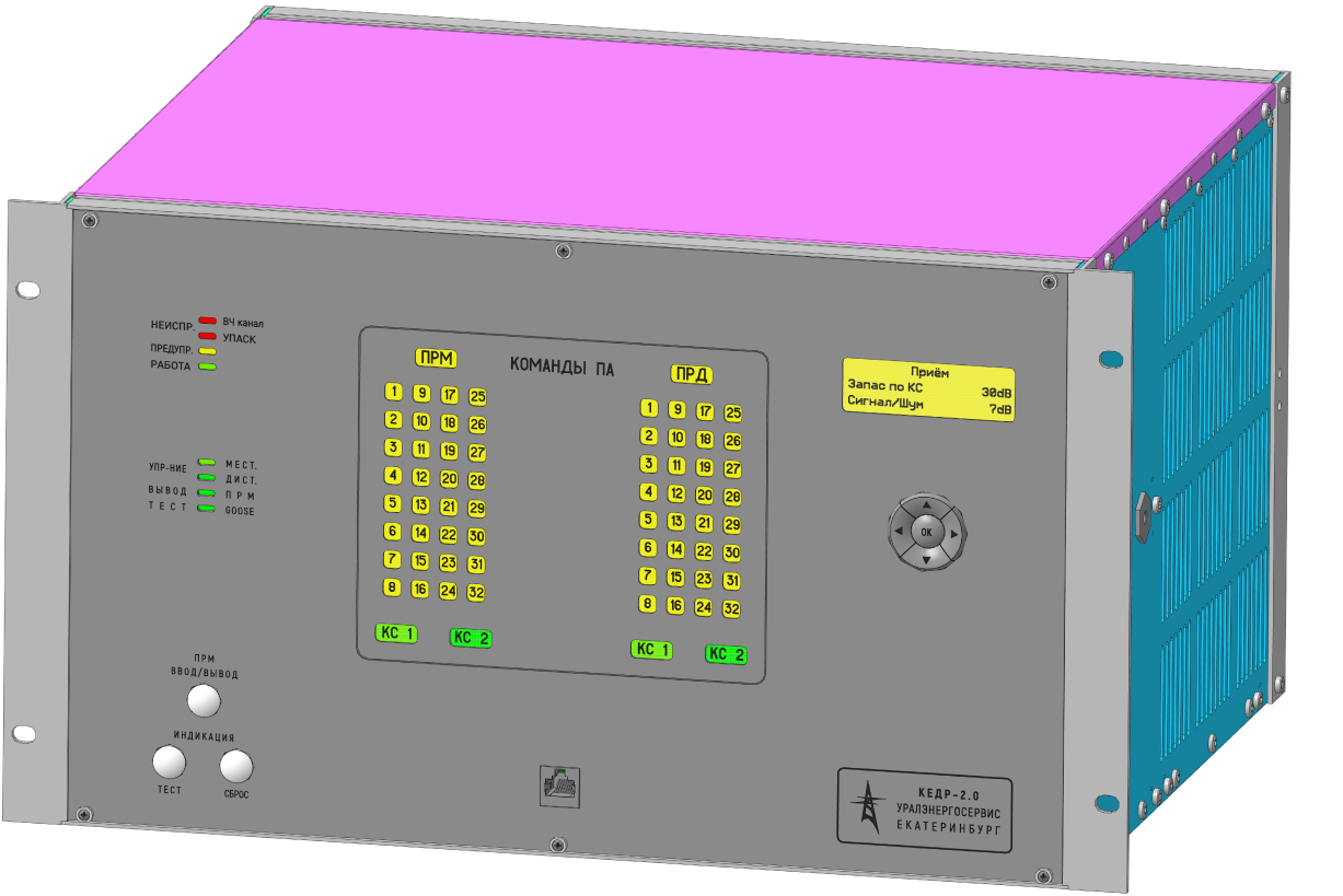 Using the application, you can create an advertising booklet for the future serial product without even having photos of the first product samples.
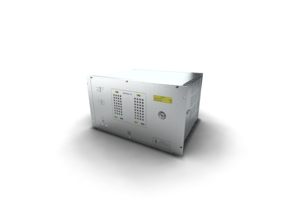
Test
After the end of product development and the release of the first prototypes, the stage of qualification testing begins. The product is checked for compliance with the declared characteristics and functionality at the production site of our company. After their successful passage, certification tests in an independent laboratory for compliance with safety requirements, electromagnetic compatibility, climatic and mechanical influences follow.It would be right to go to these tests, having on hand the positive results of preliminary calculations. In this regard, the APM FEM strength analysis system is of interest for a preliminary assessment of the structural stability to sinusoidal vibration in the range from 2 to 100 Hz for subsequent field tests for compliance with the requirements of GOST 30546.1-98 (earthquake resistance). Perhaps our interest in this topic will be supported by testing laboratories, since in justified cases it is allowed to conduct seismic tests using the calculation method. Currently, ANSYS software is used for this.Finish line: preparation of design documentation
By the beginning of mass production, you should already have a set of design documentation drawn up according to the requirements of ESKD and approved by the General Customer. Work on its preparation is carried out by employees of the department on the instructions of the head in several programs:- design documentation for the installation of printed circuit boards is drawn up in Altium Designer using the newly developed editor Draftsman
- assembly drawings of blocks and working drawings of complex parts are performed in KOMPAS-Graph
- design documentation for front panels, nameplates and stickers is carried out in CorelDRAW and is transmitted to contractors only in electronic form.
Prospects for the drawing technology
I would like to draw the attention of ASCON developers to the trend of transition to drawing technologies. When working with foreign suppliers of cabinet equipment, we have already moved from the coordination of drawings to the coordination of 3D models by cover letter.Already, KOMPAS-3D allows you to store in the model the information necessary for the manufacture of the product: dimensions (including with tolerances), roughness (including unspecified), bases, shape tolerances, leader lines and others. All this information is visible directly in the workspace, but the technical requirements are opened in a separate tab.In our opinion, it would be convenient to provide the user with the opportunity, if necessary, to place the technical requirements in the space of the 3D model of the product, in one of the three base planes. So that when you open a file in KOMPAS-3D or in KOMPAS-3D Viewer, all the necessary information is displayed on the screen and always before your eyes. In this case, the user should be able to move the technical requirements in the plane and change the text parameters.In the future, we plan to consider abandoning assembly drawings in favor of 3D assembly files at our production site. This will simplify the reading of design documentation, and therefore, will facilitate the process of placing products on serial production.It would also be interesting to see the synchronization of the Standard Products directory with the 1C accounting product to ensure uniformity of the data used in the enterprise.PS It so happened that the writing of this article was preceded by a month of hard work with the new version of KOMPAS-3D v18. I understand that this is a separate topic for discussion, but I can’t get around it.
Our main interest was in the processing of "heavy" assemblies with more than 10 thousand parts. ASCON developers announce a breakthrough improvement in performance in the 18th version. Comparative characteristics with earlier versions look very attractive. For this reason, I wanted to evaluate the capabilities of the new version in the realities of our enterprise.
The results are encouraging. The rebuilding of "heavy" assemblies is now measured in tens of seconds. While before the rebuilding could last tens of minutes. Significantly reduced the time to open and save files. In general, the system behaves noticeably more stable. The author is Yevgeny Fofanov, Head of the Department of KTOP Uralenergoservice.
 Source: https://habr.com/ru/post/undefined/
All Articles