Mass production of electronics in Russia. Test Automation
I continue to talk about our experience in organizing serial production of commercial electronics.The previous article was about the history of the product. There are a lot of statistics obtained as a result of using test stations. But little about what the stations themselves are. Today - more about how we automated the functional testing of printed circuit boards in production and how the test station is arranged, which helps us in this.What we wanted to achieve:- Total control. Check every board, not selectively.
- Reduce the influence of the human factor. The effectiveness of testing should not depend on the qualifications and personal qualities of the performer.
- Integration with production. Testing should be part of the overall manufacturing process.
- Firmware. The device should come out ready for further assembly in the housing.
- Accounting and labeling of released devices. End-to-end serial number assignment. Printing of stickers for further identification.
- All this should work quickly.
To do this, we decided to expand the capabilities of the tester, which we wrote about here , and developed a testing system. The system provides the interaction of test stations, production infrastructure, server platform and users. Allows you to store, process and provide access to information for the testing operator, production manager, system operator, other users. In the future, we plan to add the ability to remotely control test stations (change the test plan, firmware version, etc.).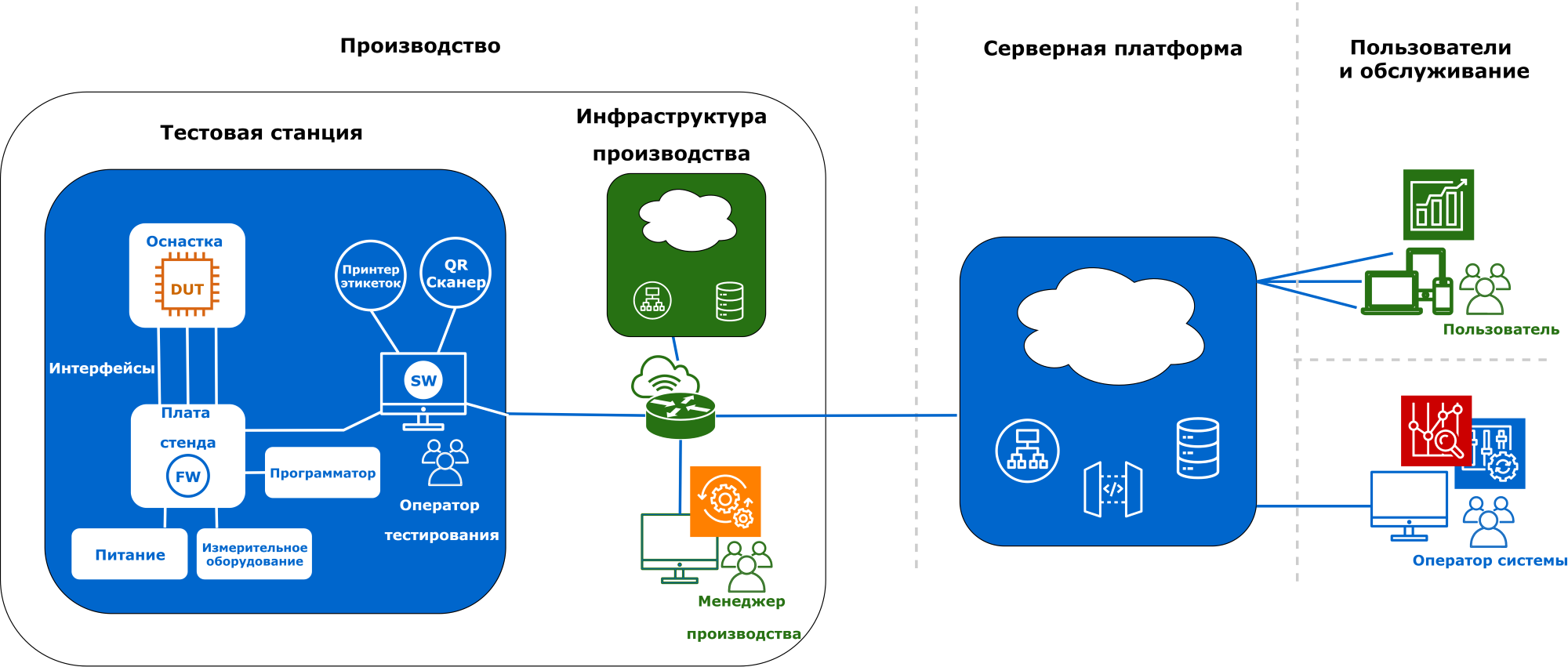
DUT (device under test)
A little about the device that we are testing. Simplified block diagram: This is a telemetry module that runs under the control of a microcontroller. It has several interfaces to the control object, communication with the server, indication and controls. The module works both from external power supply and independently from the battery. In TK, we painted a detailed test plan for a test station, here I will briefly give the functions and methods of testing: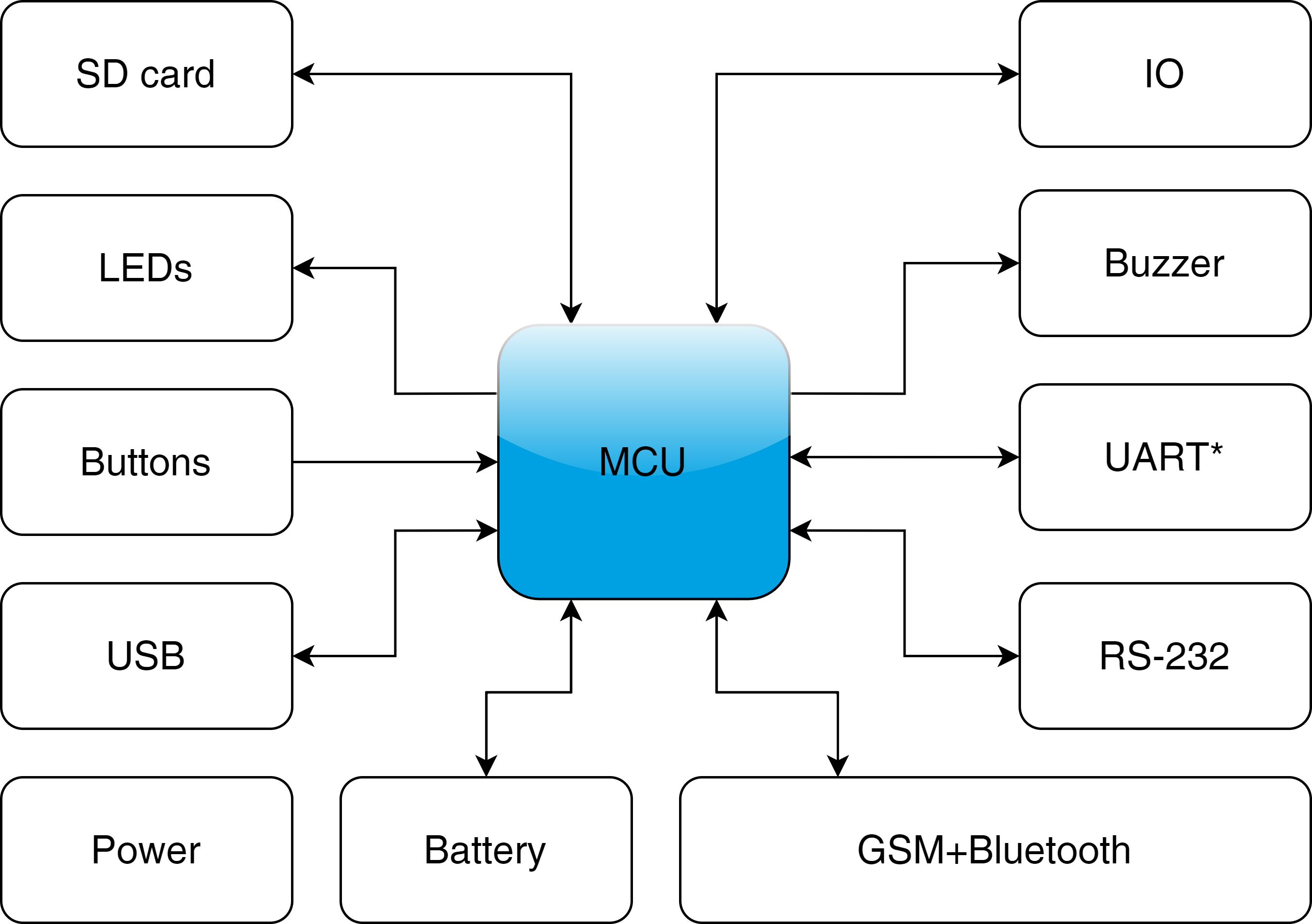
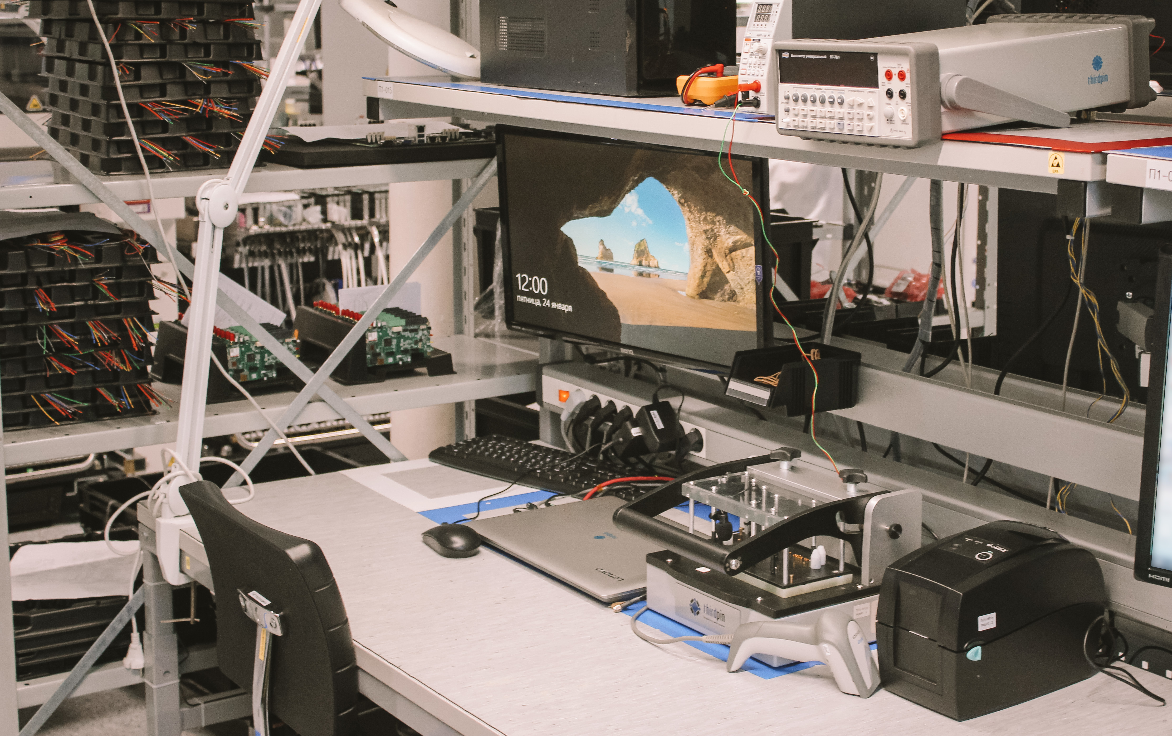
Test station
The test station consists of equipment, standard instruments and a laptop that controls all this. Almost all devices are connected to the laptop via USB.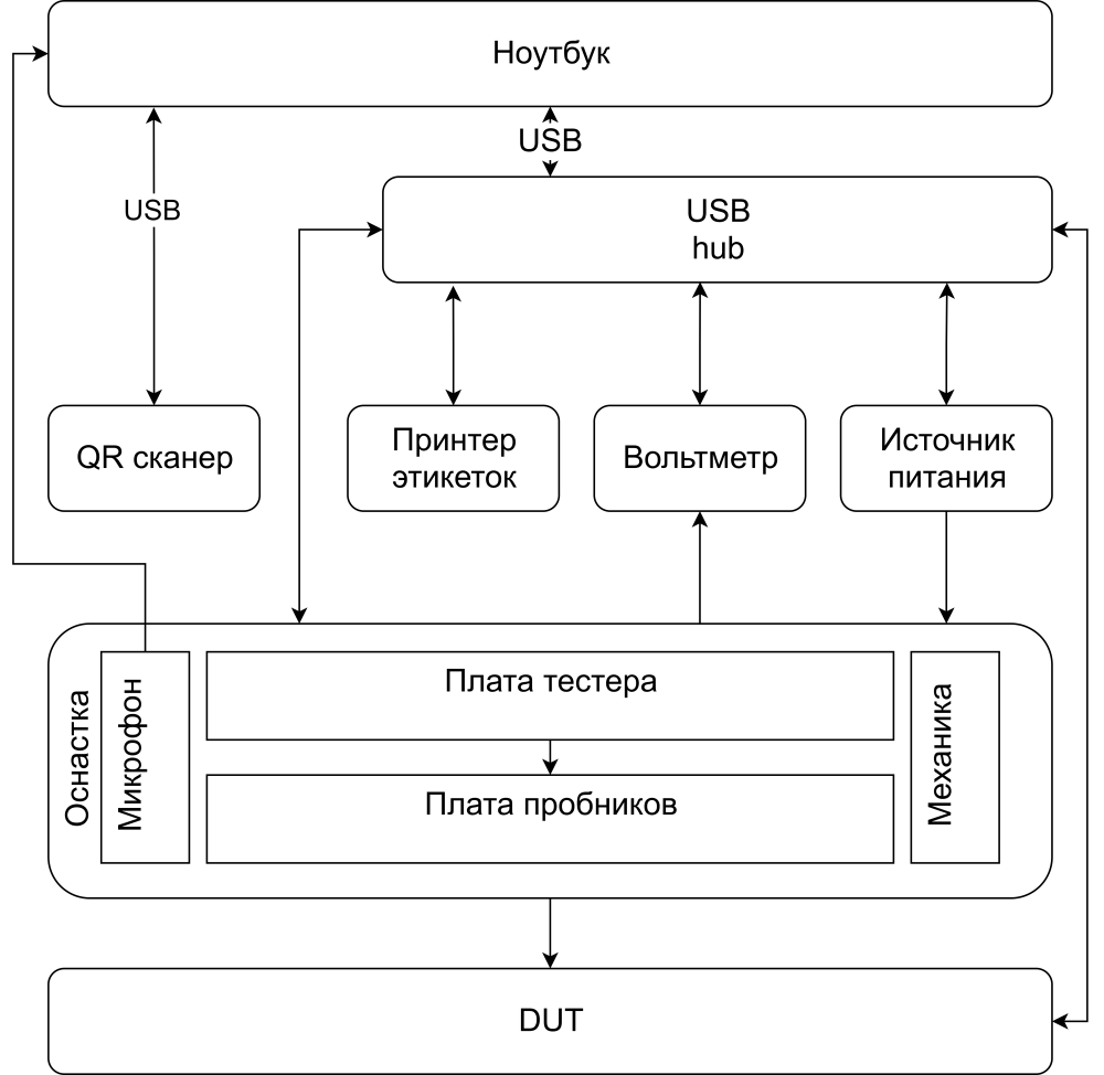
A laptop
When we chose a laptop model, we thought that we would just deploy pre-debugged software on them. Therefore, the laptop does not need much performance. So we bought cheap laptops with WIN10. Do not do so. Debugging on the target hardware is inevitable. It is much more convenient to work with normal hardware, especially since the cost of a laptop on a project scale is not so fundamental.Windows was not the best OS for our needs. It is difficult to achieve the identity of several stations with it, it is difficult to completely and permanently stop updating. So we came to the production to deploy a testing station:
Windows also threw one task over Bluetooth. When trying to connect a new device to the Bluetooth of a Windows laptop, each time it asks the user for permission. We could not get around this request softly and made Bluetooth inside the stand.The following operator panel works on the laptop: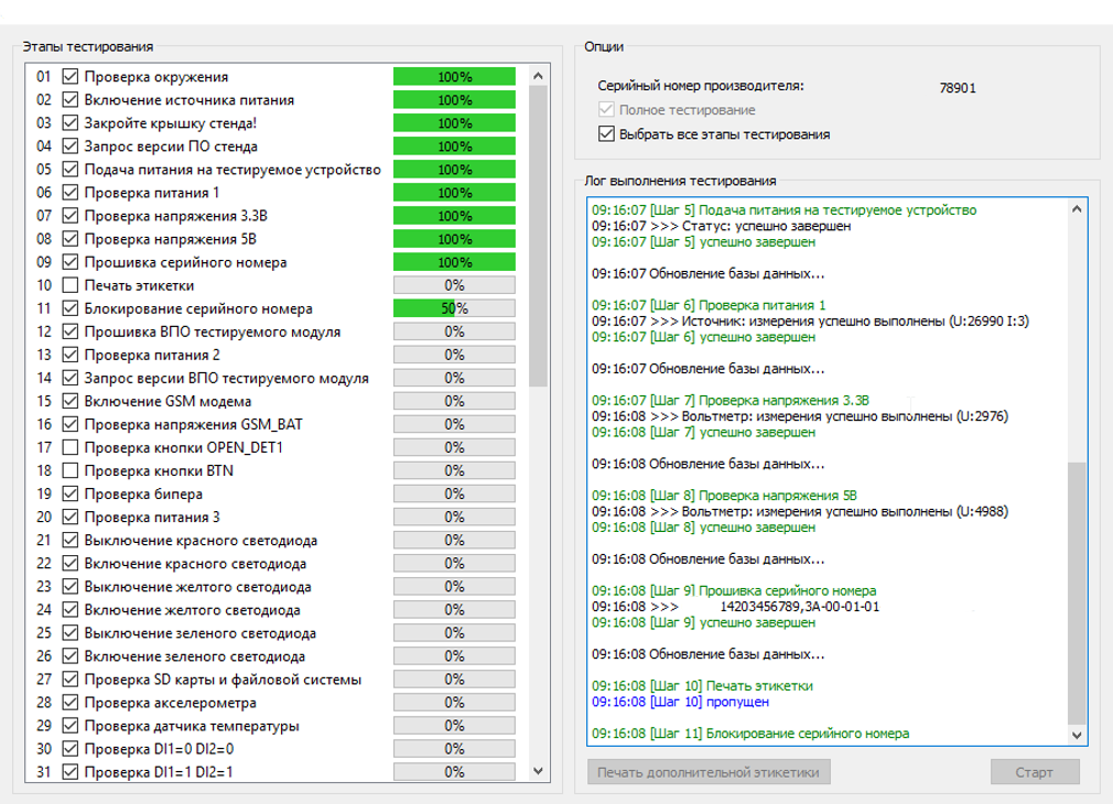
Testing begins by scanning the barcode on the board. The testing process is the sequential execution of steps in the test program, each of which has a number, name and status of execution. (left side of the interface) If necessary, you can uncheck the execution checkbox at separate steps and they will be skipped. As it progresses, the testing program displays additional information in the Test Execution Log window (on the right) about the status of the current step. Label testing ends.The test station board and DUT are connected to the laptop via USB and are exchanged using the modbus protocol.Stress Testing
One of the main requirements for the work of a test station in production is reliability. She must not skip marriage and not reject suitable products. To identify rare failures, you need to run testing many times. Therefore, we began to do load testing. The autoclicker launches the GUI and simulates the work of a stand operator. The total number of stress tests is more than 20 thousand.USB hub
It turns out that there are no trifles in automation. All our devices are connected to the laptop via USB. Sometimes they “fall off”. Most often, the test station board freezes, of course. First, we fought with these hands and poked the wire in the laptop. Then they learned to reboot the hub softly, while it resets the power and reconnects all devices. Now, each test begins with reconnecting all USB devices. Usbdeview helps us with this . It turned out that not all hubs do this, and almost exactly the same kind of hub does not know how. We buy exactly the same.Even the order of inclusion of devices in the hub affects stability, the user guide has a special section with an illustration of how to stick:
Rigging
The equipment consists of mechanics, a testing board (1) and a probe board (2).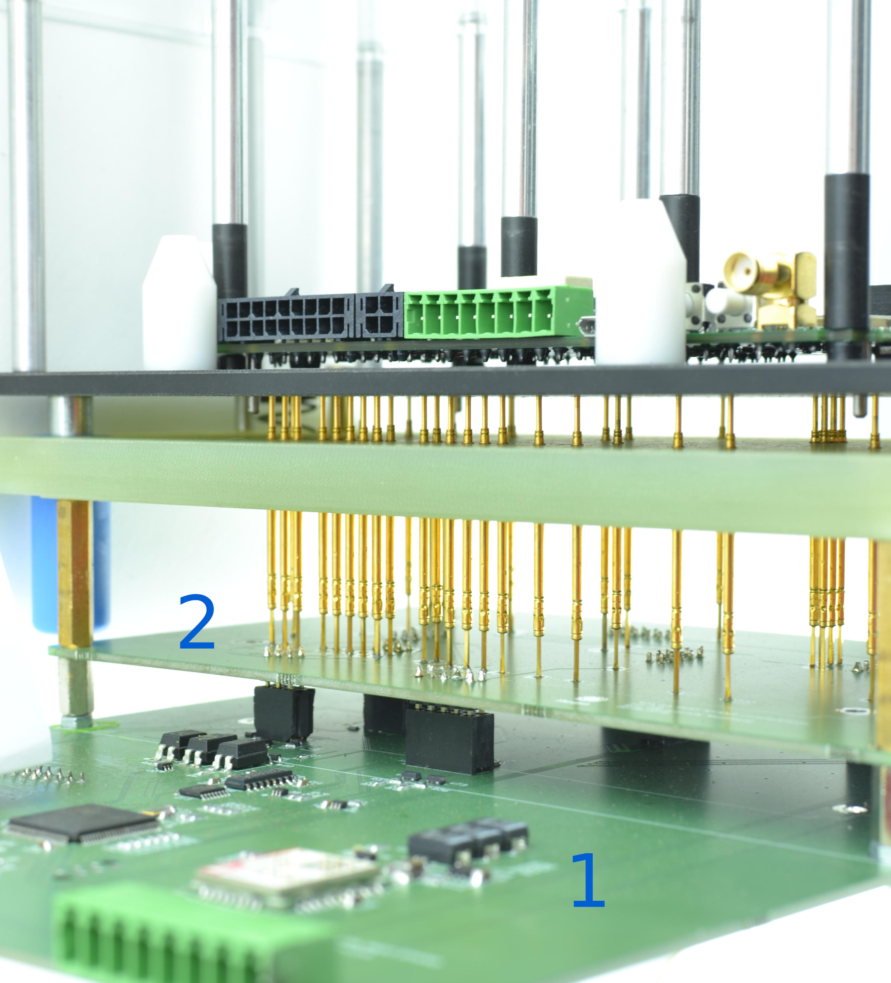
Mechanics development
Once we started making our own mechanics, worked out several options: Developing your mechanics from scratch is quite expensive. Solutions seem to be 100% working, and then something always sticks in the mock-ups, it bends somewhere, and various improvements are constantly required. In the end, we came to the conclusion that it is much more profitable to use ready-made nodes. To reduce the cost, you can use the same equipment on different projects, processing only plug-in modules. On this project, we used the Ingun MA260 snap -in . The process of developing mechanics in our case can be divided into the following stages: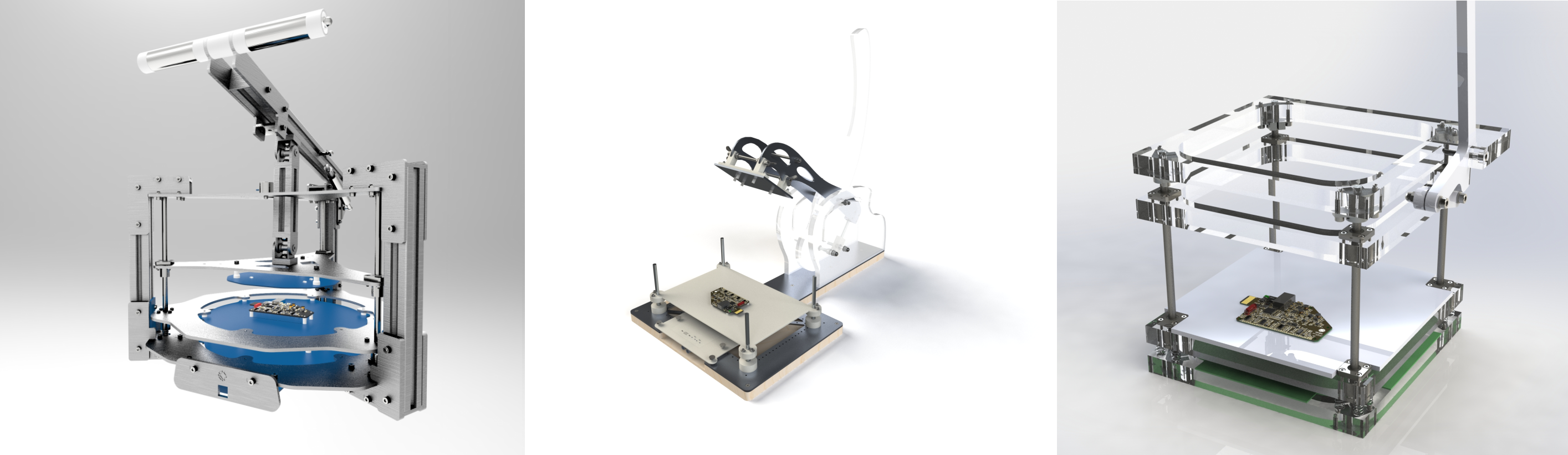

- Choosing the right size tooling
- Layout - DUT and PCB Placement
- Arrangement of guiding elements, emphasis and probes
- Unloading the design of circuit boards for tracing
- Verification with finished PCB models
- Creating Drawings
- Parts Production
- Assembly check
- Repeat the cycle (until it turned out the first time)
Here is an example drawing of a movable plate: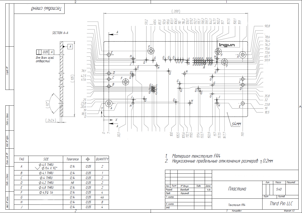
Test Station Boards
There are different approaches to the implementation of connections between spring-loaded contacts and devices of the test station.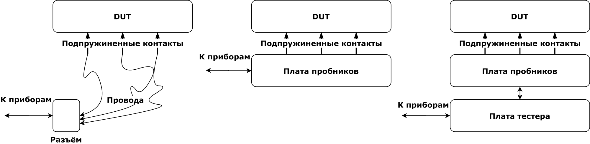
- No circuit boards inside the snap. The wires from each spring-loaded contact go to a common snap-in connector, and already from it the signals are distributed to the devices. Installation of wires can be very time-consuming, changing such equipment is associated with a risk of damage to the wires.
- With one sampler board. The probe board performs two functions: mechanical and electrical. The probe holders are sealed in the holes on the board, and the test signals are output to the connectors to external devices. But there are specific interfaces in our DUT, and we need an additional board inside to work with them.
- With probe board and tester board. The tester board is a separate device with its own microcontroller, which receives commands via USB from a laptop. It can be combined with a probe board, but due to the large number of holes for probe holders, this is inconvenient in terms of tracing.
The tester board performs the functions of:- Formation of special interfaces
- Logical signal processing.
- Switching analog signals for an external voltmeter.
- Monitoring and Power Management DUT.
- Detecting the presence of DUT in a snap.
- Execution of test sequences.
- DUT firmware (standard programmer is fixed on the board).
Wires
There are a lot of wires. Several of them are plugged into the DUT by hand before testing:- antenna cable with quick-connect SMA
- micro USB
- battery
We decided to stick the battery with our hands, because at the time of the creation of the equipment we thought that each device would be tested with a complete battery. In practice, this turned out to be redundant, we didn’t come across any faulty batteries, so the operator uses the same battery.When closing the snap, there is a risk of breaking the wires. At the same time, it is also impossible to make them very briefly - you need to give the operator a chance to stick them without getting into the equipment himself.The quick-detachable SMA turned out to be no faster than usual, the production got rid of it.Looking back, it was necessary to make automatic connection of these interfaces.Through-hole connectors we connect through the protruding pins on the back of the board. How to get to USB? To do this, there are special Side approach mechanisms that allow you to plug the simulator of the connector into the test node, or bring spring-loaded contacts.Microphone
First, we used an operator to test the speaker on the DUT. There is a command to peel on the DUT 1..3 times, and the operator must select the correct number of peaks in the pop-up window. Our programmers were constantly mistaken even when setting up a stand, and in production - in general, a bad job. As a result, we added a microphone, it is mounted like this, directly opposite the DUT emitter.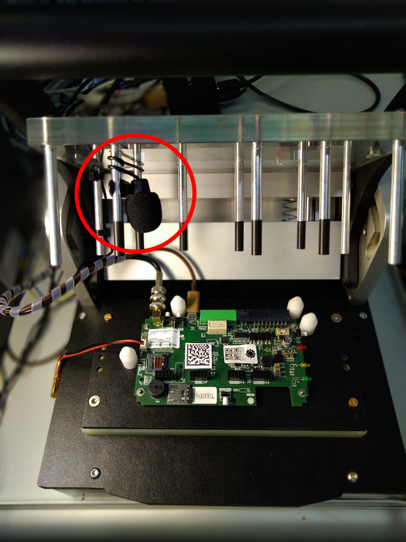
Data storage and visualization
The testing process begins with communication with the server. We want to know about everything that happens with our devices in production. So there is no connection - no testing. To do this, a database is deployed on the server. For any operation with the station, a record is entered into the database, the start, end and all the results of the testing steps are recorded. So later we can do unloading with interesting statistics, as well as learn in detail the fate of a particular instance. For operational control of production, we have a user site with the most interesting metrics: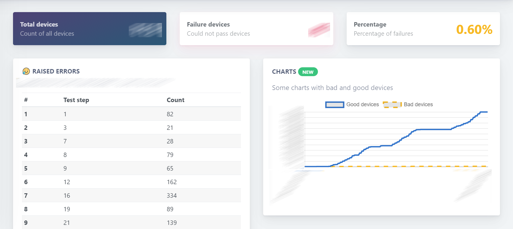
It shows the total number of devices tested, the number of defective devices, their percentage. Below is a table with a breakdown of the marriage, the number of errors in the test stages. At the bottom right is the Test Graph, it shows the “good” and “bad” devices in time with an increasing amount. Interruptions in testing (horizontal sections) are clearly visible on it. By the slope of the schedule, you can judge the pace of production and see in advance whether production is on time, or is it time to adjust the plan.Transportation
Transportation of test station equipment to production looks like a one-time operation. In practice, they move quite actively, sometimes between production facilities, sometimes return for repairs to developers with all possible means of transport. In general, packaging requirements are increased. For transportation, we use these Peli 1637 cases .We lay equipment with a bubble, we fill the empty space with it. We watched from the porthole loading our equipment on the plane. The mass of the test station gross 27 kilograms. We thought something would definitely break, but both the suitcase and the filling all survived without loss.Reference sample
When deploying a test station in production, it is good to have a sample of the device with which it was tested during development (guaranteed working sample). We train production personnel with him. With it, we check the interaction with the server. Further, during the batch testing process, there are also problems, and first of all there are doubts about the work of the test station itself (sometimes justified), and the reference sample helps to find the reason.Project labor
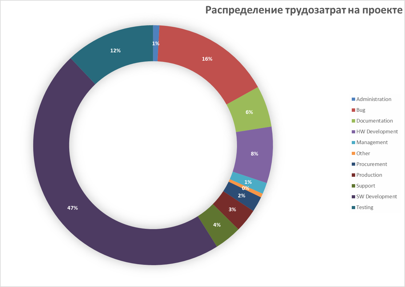
Iron development (equipment, boards inside) - 8% of the total labor input. If you plan to make a test station - do not take the hardware as the main part in terms of cost and complexity.Software (Development, bugs, testing) - in total they give 75% of all labor costs.For this product, the production stage exceeds the development of the device in complexity and cost.We are currently working on a unified testing platform. Unification will affect hardware, firmware, and the server platform. This will reduce costs and time for the development of test stations for the new devices of our partners.Surely I forgot to write about something important, welcome to comment.PS We did not extend the company’s blog on Habré, so subscribe to me if you want to continue to monitor our successes.Source: https://habr.com/ru/post/undefined/
All Articles