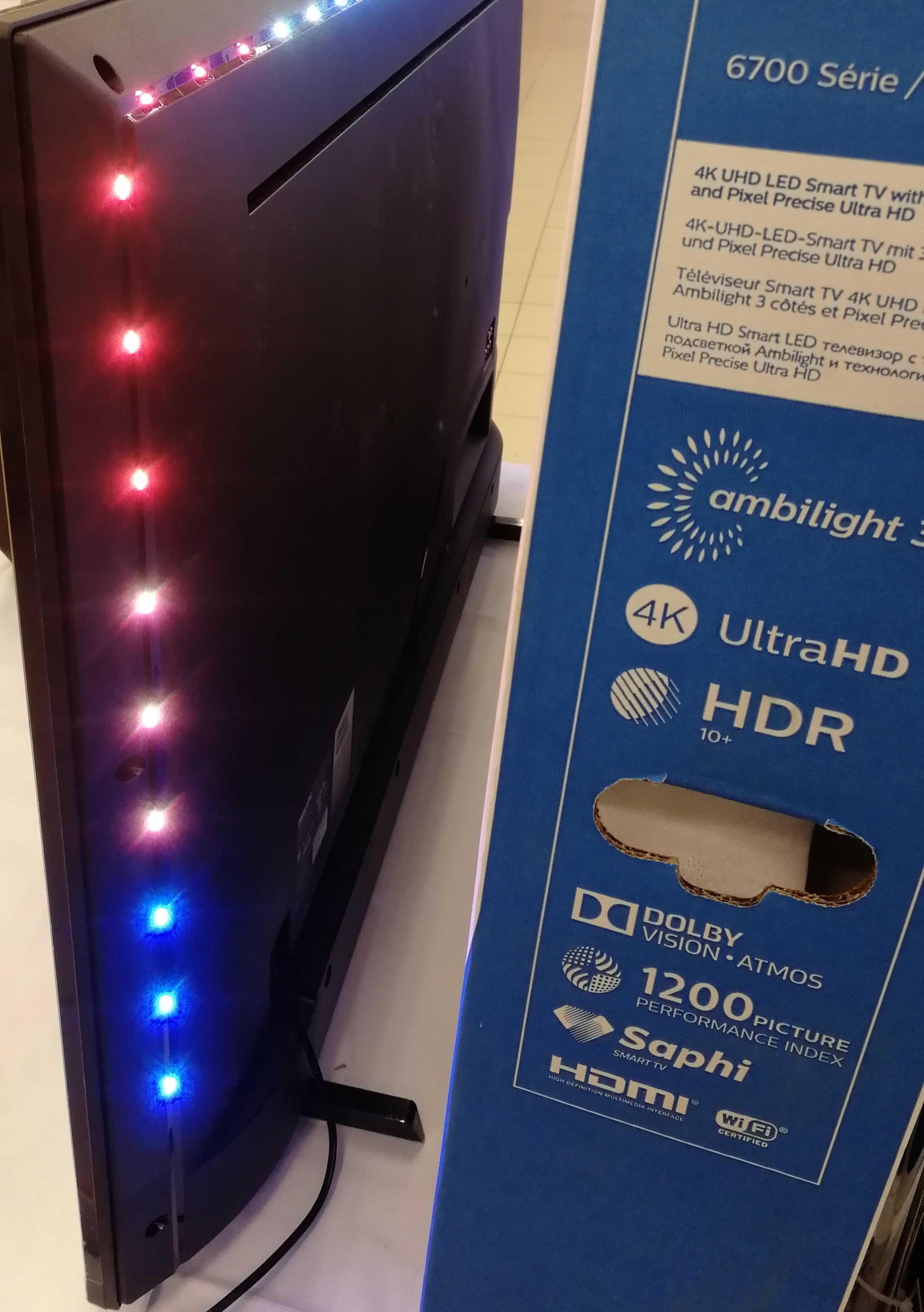
 This is a 50 ”TV with 37 RGB dots of adaptive backlighting on the top and sides of the screen. How to make a similar adaptive backlight for any screen or TV is a hackneyed topic, but quite relevant for a number of reasons.First of all, everything is changing. A couple of years ago there was no project working without software or hardware crutches. In any case, I have not seen such publications. Those that are described on the Internet are either lost relevance due to the obsolescence of software or hardware platforms, or they implement this technology only with respect to monitors connected to a PC.Secondly, there are no and will not be Samsung, Sony, Elge and other TVs supporting this technology in the market, as it was patented by Philips for many years to come. And finally, all the solutions “out of the box” available on Ali and others like him have a number of limitations in the flexibility of settings and adaptation to the frame size of video content, color gamut adjustments, etc., being just a hardware crutch analyzing an external signal and working only on the formation of the backlight.
"Hardware" frame capture option
If you don’t talk about theoretical options for refinement and modernization of the television receiver itself, you must agree with the fact that in any case you will have to process the HDMI signal - i.e. It will be used for frame analysis and backlighting. Here, only two implementation options suggest themselves: with signal processing from any source (like lightpacks with Ali) and with the implementation of the source itself as a TV set-top box with adaptive backlighting.In the first case, we get some kind of versatility - you can connect a game console or some kind of player to the device. In the second - we collect this same "some kind of player" with a built-in backlight function. While experimenting, I implemented both options, but here I will focus only on the second, and here's why: In the given block diagram of the first variant, the HDMI signal from any source comes to the splitter, where it is divided into two outputs. From the first, content is played on any TV receiver or monitor. From the second, the signal simultaneously enters the hardware scaler, where it is converted into an analog signal with low resolution frames - 320x480. An analog signal is sent to a hardware USB grabber, which takes “screenshots” of each frame and transfers them via USB to the input of a single-board mini PC - Raspberry Pi 3 B +. The software on raspberries analyzes frames using the Hyperion program and, through one of the GPIO outputs, provides control sequences to the input of an address tape like WS2812B or APA102. All this worked fine, but it has a couple of drawbacks in the form of a heap of iron with connections and a slight delay in issuing a backlight signal.The delay was noticeable only on test videos with a sharp change of colors in most of the frame. Otherwise, no complaints, except for the cost of all the iron in this implementation:Raspberry Pi 3 B + - about $ 55.Radiator Case - $ 14.Active HDMI 1080P splitter for 2 outputs - $ 15.HDMI 1080P To AV Scaler - $ 15.EasyCap USB grabber - $ 18.Power supply - about $ 10.32GB microSD card - $ 10.Connecting cables and other small things - about $ 10.Total, not counting the address tape - almost $ 150.It’s not that such an option immediately into the furnace - it may well come in handy for organizing backlighting on some large prefabricated screens in advertisements or presentations, and the price is not the worst for the result - but for home use I settled on the second option - in Mostly “software”. It came out easier, cheaper, more compact and faster. For commercial use, it can also be quite suitable - the Raspberry Pi with the player can be successfully used in projects where you need to automatically play cyclically and seamlessly play some content from the moment you turn it on, turning off the player, again automatically - according to the schedule at the end of the day. Having written a small script, we get an advertising device with the function of adaptive backlighting of any screens, at least ten-meter high. But back to home use ...
"Software" option capture frames
The functions of the media center and backlight control will remain behind the same Raspberry Pi 3 B +, and all connections will now be reduced to connecting several connectors - power, Internet, backlight and HDMI to TV. No more than any other TV set-top box: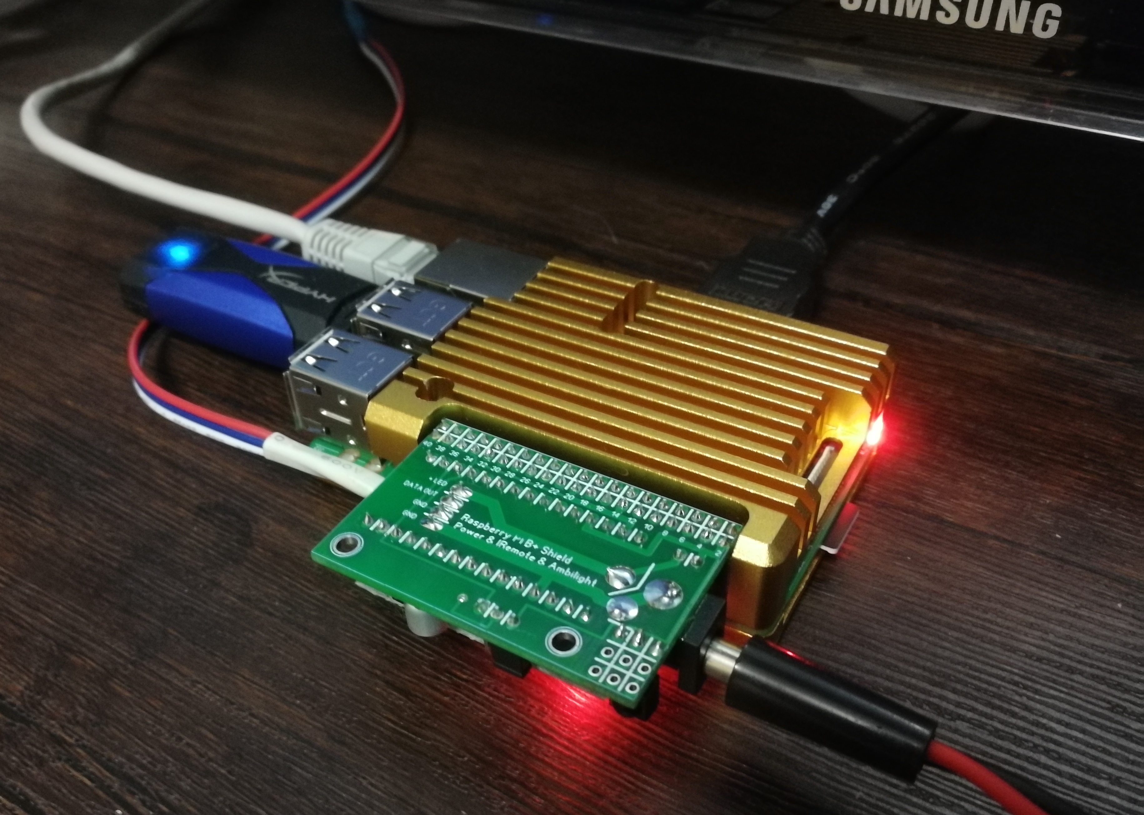 Looking ahead, I want to note that the Raspberry Pi 3 B + turned out to be a very universal TV set-top box-media center with all the necessary capabilities of such a device, plus a flexibly customizable adaptive backlight for any modern (and not so) TV having an HDMI input.The basis of the software is the open Libreelec OS, specially sharpened for the Kodi player. The project site contains all the necessary information.About the capabilities of one of the most powerful and flexible platforms for playing video-audio content, IPTV, etc. can be read by scoring in any search engine "kodi description of opportunities." There is a lot of information in Russian on this topic. I use, perhaps, 1/10 of all the platform features and this is enough for me. The platform is actively supported, has a responsive community. Therefore, we read, we study - on the wiki of these projects and on the forums there is almost all the necessary information and answers to questions. We take the distribution kit and installation and configuration instructions on the Libreelec project website. Since the OS is cross-platform, do not forget that our project is built on Raspberry.Violating the strange, but well-established tradition of starting such publications with a description of the types of address tapes and how to clumsy stick them on the back walls of home TVs, I will start by installing and configuring single-board software. Unfortunately, making step-by-step instructions for setting up is almost impossible - it would take half a hundred pages of text without screenshots. In addition, the player’s platform is actively developing, OS and Kodi versions are changing, current information - it soon ceases to be so. Therefore, here are only the main points plus links to sources of useful information.To configure the software part of the backlight, control the IR remote control and the player itself, you need to have an initial idea of how the Libreelec directories are arranged, how the local network works, the console, what to do with the command line, etc., as we will do some things in the process manually. Through the installers on the microSD card, only the Libreelec OS and the add-in for highlighting - Hyperion, will be installed.Since the Raspberry Pi does not have a built-in real-time clock, BIOS and backup power, all that is needed to work is located on the microSD card. To install the OS on the card, you must download either the NOOBS package from the Raspberry project website (at the time of installation I used build version 3.2.1) or a special tool - “LibreELEC USB-SD Creator” .The memory card should have good read and write speeds - that is, be at least grade 10. In terms of volume, Libreelec OS takes up little space, 16GB cards will be quite enough for work, if there is no desire to purchase more volume. It can be used to store any content.In the case of NOOBS, the contents of the zip archive are unpacked to the root of a microSD card formatted in FAT32, the card is inserted into the slot of de-energized raspberries, the power is turned on, and then, choosing the necessary OS in the installer and following the instructions, we deploy Libreelec. However, the platform developers recommend installing using LibreELEC USB-SD Creator, which itself downloads and writes the distribution package to the card, then the card is also inserted into the raspberry slot, where the installer deploys the OS after turning on the power. In this case, the sections of the card are reformatted, after which from under Windows you will not see the entire real volume of the media. If for any reason you need to return the partitions to their original state, you will first have to clean the card with the standard Windows utility - DiskPart,then, in the "Disk Management" section, create a new partition on the free space of the medium and format it.To simplify the installation and configuration of the OS, I temporarily connected a separate monitor and keyboard with a mouse to raspberries.Also, to configure and configure raspberry software, you will need its connection with a PC and Internet access, preferably wired. The software installed on the PC for connecting via SSH - PuTTY and WinSCP, as well as the Java virtual machine (jre-8u231-windows-x64) and the Hyperion daemon configurator - HyperCon (HyperCon.jar). You can use another convenient file manager with panels, for example - Total Commander. Where to download and configure - a lot of information on specialized sites, it is enough to search for information with the search query "work with PUttY and WinSCP". The Hyperion project also has its own forum and wiki.In this screenshot, there are three ways to connect raspberries to a PC under win via SSH - through the Putty console, WinSCP file manager and Total Commander:
 Libreelec admin account by default has a username and password root @ libreelec, which are best changed for security reasons. After a successful installation in the system settings, we perform simple actions - turning on SSH, SMB, assigning a static IP, disabling updates:
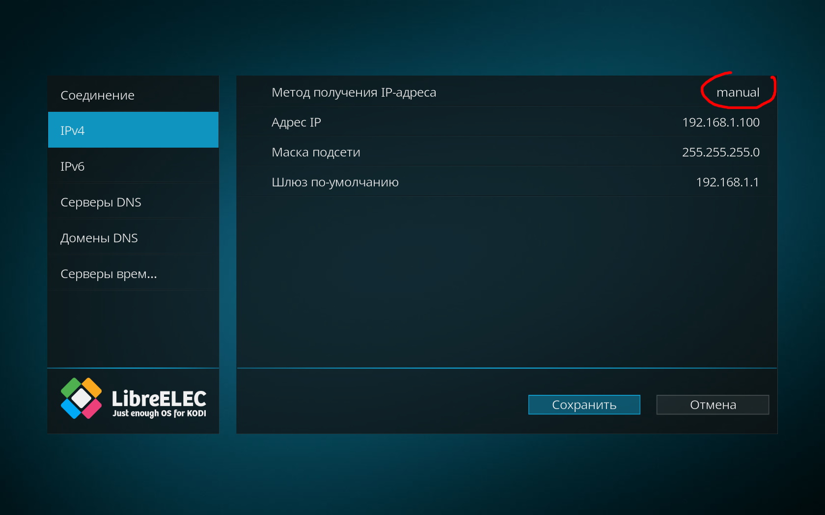 It is assumed that raspberries are connected to your home network, and you can find out the IP address of the devices connected to it on your home PC. I turned off updates so that the once configured adaptive backlight system does not crash if the developer changes any of the related components in Libreelec.In the system settings in the services you need to enable SSH and enable password authentication, also set the minimum version of the SMB2 protocol, the maximum - SMB3. SMB is needed in order to see the Raspberry Pi directories and the flash drives connected to it from the PC:
 Under Windows 10 on the PC, you will have to find and enable SMB support in the settings, since it is disabled by default in it: We
 also search and add in the settings Russian keyboard layout. Nothing will happen to the physical keyboard - there will only be input in English, but in the virtual on-screen keyboard it will be possible to enter text in Russian. For convenient access to directories on a microSD card and flash drives connected to raspberries, you can create and place a shortcut with the address of the remote directory on the toolbar in Total Commander:
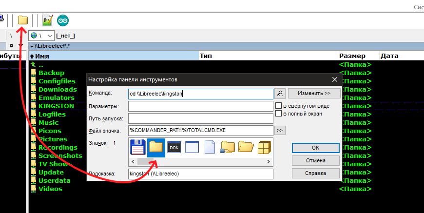 Files on the local network will be transferred at a speed limited by the bandwidth of your home router, and much faster than in access via SSH. In any case, copying a movie or music in this way will be more convenient than carrying a USB flash drive from a set-top box to a PC. You will see the internal directory structure in / storage on the raspberry card and the drives connected to the USB ports. With a wired connection, I have 100 Mbps. through the router, the maximum download speed of files from a PC to a USB drive in raspberries was about 12 MB / s, which roughly corresponds to the bandwidth of my wired connection.If necessary, in the future you can deploy to your PC any home media server (UPnP, DLNA) for streaming content directly from your PC.After installing and configuring access to raspberries from a PC via SSH using the PUttY and WinSCP programs, you can proceed to install and configure the Hyperion daemon. There must be a Java virtual machine on the PC.Everything will work something like this - at the start of Raspberry, a special program, Hyperion, will be launched in the background with Kodi in the background. She will analyze all the video frames, and depending on the settings recorded in the configuration file - manage the address tape through one of the raspberry's GPIO outputs. That is, after the settings, everything will work autonomously, no communication or interaction with the PC is required. But to quickly create a configuration file and install Hyperion on raspberries, there is a convenient configurator that runs on a PC. This program will help you quickly create a configuration file for the daemon to work, download and install it in Raspberry and check the system’s functionality using a convenient graphical interface.
Hypercon
The configurator is called HyperCon, it does not require installation, we just run the executable file HyperCon.jar on the PC and we see this window: On the right side there is a virtual screen for which the backlight will be adjusted - color capture zones, their numbering (starts from 0), direction, location padding, overlap and depth. In the left part there are five tabs with settings.Briefly on the tabs of the configurator:Hardware (hardware)
- device -> Configuration Name - any convenient name for the current configuration
- device -> Type - chip type of the address tape, module, or something else
- device -> Amount LEDs - number of addressable pixels (how many LEDs in the tape)
- device -> RGB Byte order - colors in the protocol used
Construction (arrangement of light sources)- –> (led top left ) —
- LEDs horizontal ->
- LEDs Left->
- LEDs Right ->
- Bottom gap -> ( )
- 1-st LED offset -> .
Image process ( )- Image process -> Horizontal depth – , %
- Image process -> Vertical depth – , %
- Image process -> Horizontal gap – , %
- Image process -> Vertical gap – , %
- Image process -> Overlap – , %
Blackborder detection - Sensitivity and processing mode. It works in theory like this - the demon analyzes the edges of the screen at the specified level and calculates the width of the dark edges to exclude from the processed zones. This is for cases when a widescreen picture is played.Process (frame processing)- Smoothing -> Enabled (check box to enable anti-aliasing)
- Smoothing -> Type
- Smoothing -> Time
- Smoothing -> Update freq (refresh rate)
- Smoothing -> Update delay (delay before updating the frame)
- Color calibration - intuitive items that allow you to set the minimum and maximum glow level, saturation, temperature, background glow level without signal, separately for each of the 3 primary colors.
The marked checkbox Send Continuous allows you to see changes in the configuration process already on the assembled structure.Grabber (Grabber - frame grabber, the most interesting tab)- Internal Frame grabber (Software grabber)
- Internal Frame grabber-> Enabled (checkbox for enabling internal grabber)
- Internal Frame grabber-> Width
- Internal Frame grabber-> Heigth (zone height)
- Internal Frame grabber-> Interval
- Internal Frame grabber-> Priority Channel (priority of this channel)
Some clarifications are needed here. The trick is that we are making a media player based on the Raspberry Pi, which will itself play content from the local network, flash drive, or IP TV on the LibreElec platform. Since the content is already spinning with the raspberry player, the capture will occur programmatically, without an external EasyCap grabber, and the demon will deal with the frames itself, since in this case the signal source will be the HDMI output of the Raspberry Pi itself. It is possible to use the same external grabber for another source, without disconnecting the internal one - channel priorities are provided for this, this is the last item to configure the software grabber. The higher the number, the lower the priority of the channel.Exactly so, there is no mistake.- Grabber V4L2 (Hardware Grabber Driver Settings))
- Grabber V4L -> Device ( USB , — /dev/video0 )
- Grabber V4L -> Input ( — 0 )
- Grabber V4L -> Width ( — -1 )
- Grabber V4L -> Heigth ( — -1 )
- Grabber V4L -> Frame decimation ( )
- Grabber V4L -> Size decimation ( )
- Grabber V4L -> Priority Channel ( )
- Grabber V4L -> 3D mode ( 2D/3D)
- Grabber V4L -> Crop Left ( )
- Grabber V4L -> Crop Right ( )
- Grabber V4L -> Crop Top ( )
- Grabber V4L -> Crop Bottom ( )
- Grabber V4L -> ( )
External ( )- External -> Kodi Checker ( Kodi, . . , , )
- External -> Json/Proto/Boblight Server ( , )
- External -> Booteffect / Static color ( - )
- External -> Json/Proto Forvard ( , )
SSH ( Raspberry Pi)- SSH – Connection -> System ( , Raspberry Pi)
- SSH – Connection -> Target IP (IP Raspberry Pi)
- SSH – Connection -> Port ( — (22))
- SSH – Connection -> Username/password ( – , Raspberry Pi)
- SSH – Connection -> Connect/Disconnect ( - Raspberry Pi)
- SSH – Connection -> Show Traffic ( )
- SSH – Manage Hyperion from HyperCon -> Inst/Upd. Hyperion ( Raspberry Pi . sudo get-install, Raspberry Pi, HyperCon-)
- SSH – Manage Hyperion from HyperCon -> Remove Hyperion ( )
- SSH – Manage Hyperion from HyperCon -> Start/Stop ( - )
- SSH – Manage Hyperion from HyperCon -> Get Log ( ,
- )
- SSH - Send Hyperion Configuration -> Local Config Path (Send the configuration file to the specified local location on the PC)
- SSH - Send Hyperion Configuration -> Send Config (Send configuration file via SSH to Raspberry Pi)
- SSH - Colorpicker (an intuitive palette tester - you can check the output of all colors.
- The buttons under the tabs save-load the settings of HyperCon (not the daemon configuration file itself !!)
- HELP is understandable, and Create Hyperion Configuration allows you to locally save the daemon config file for Raspberry Pi itself - hyperion.config.json
As you can see from the list above, there are a lot of customization options, and this makes the tool very flexible for any Wishlist and tasks.As an example, my tab configuration:
 In the first tab, we arrange the zones so that the backlight pixels on the back of the TV will be physically located. You can fill in the entire perimeter or part of it, set the direction, beginning, etc. The type of tape I used is WS2812B, so in the screenshot the corresponding field is selected as WS281x. The number of pixels I determined the density of LEDs on the available tape and the diagonal of the screen. The remaining tabs are as described above, and in the most recent one, we select our OS on the Raspberry Pi, configure communication via SSH and install the Hyperion daemon on a single board. Then we save the HyperCon config, create a new Hyperion configuration file, send the created config to the Raspberry Pi, start and try using ColorPicker to check the color palette. If everything matches,any content played by the Kodi player will control the backlight. The GPIO signal output is 18 (physical pin of the comb is 12).Details of all connections will be described below, after a description of all program settings.I did not configure startup, the daemon starts at the same time as the player starts. However, it was so that the backlight still did not turn on. Then we try to check whether the autostart of the daemon is registered in "/storage/.config/ autostart.sh" and try to reinstall the daemon in order to send its config to Raspberry Pi again. The program itself sends the config to theRaspberry Pi directory -“/storage/.config/ hyperion.config.json”.You can check the daemon’s operation by sending a color on the SSH HyperCon tab, checking the “Autoupdate” checkbox and clicking the stop-start button to restart it.If the daemon does not start after rebooting the Raspberry Pi, try changing the auto start in the file
/storage/.config/autostart.sh
//---------------------------------------------------------------------------------------------------------------
#!/bin/sh
sleep 5
/storage/hyperion/bin/hyperiond.sh /storage/.config/hyperion.config.json > /storage/logfiles/hyperion.log 2>&1
//---------------------------------------------------------------------------------------------------------------
thereby delaying the execution of the daemon.Remote control by any IR remote control
Since in addition to the backlight, the prefix will be a full-fledged media center - you need to fasten and configure the remote control to it. If your TV supports CEC technology (Consumer Electronics Control, i.e. the control protocol via HDMI), you can configure and use Kodi’s existing remote control with the TV to control the set-top box. Since all manufacturers call this protocol differently in their TVs , (for example, LG - SimpLink, Samsung -Anynet, Sony - BRAVIA Sync), look in your TV settings for support for this function. I do not have a very good remote control for TV, so I went the other way - took the one that was with the old TV set-top box on android (while other ordered remotes for this project are coming from China):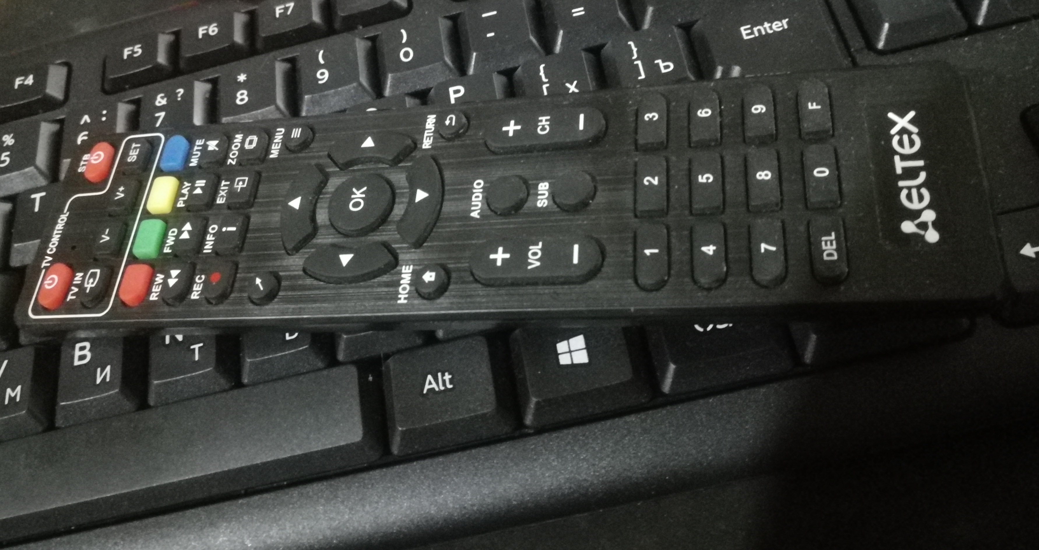 On the Raspberry comb, you will need + 5V pins, ground and signal on GPIO23 (physical pin - 16), since GPIO18 (physical pin - 12), which is configured for IR devices by default - is already busy outputting packets to the backlight.Process:To connect the driver of the IR receiver, edit the file /flash/config.txt, at the very end of which we write the line (here and below without quotes):“dtoverlay = gpio-ir, gpio_pin = 23”Connecting the IR receiver to raspberries, you need get scan codes of the remote control buttons we need and attach commands to them. After determining the protocol type in the console with the ir-keytable command, we attach the scan codes to the commands received in the console usingirrecord -l | grep ^ KEY ", manually do the mappings and create a table of this kind:table ireltex, type: NEC
0x8f64d KEY_0
0x8f642 KEY_1
0x8f641 KEY_2
0x8f640 KEY_3
0x8f646 KEY_4
And so - all the buttons and commands we need. I got 34 lines of matches. The first line is the name of the table and the remote control protocol. The following lines are the button scan code on the left. On the right, separated by a space, is the Kodi control command. And so on, in order.The table must be kept. To do this, a file is created (I called it ireltex) from which these bindings will be read. The file must be placed in the folder “/storage/.config/rc_keymaps/ireltex”, then we create the file“/storage/.config/rc_maps.cfg”, in it we write the line:“* * ireltex” (ess, but without quotes) .Using the Putty console, load the resulting table into the driver:“ir-keytable -c -w /storage/.config/rc_keymaps/ireltex”, reboot the Raspberry Pi and change the last line in the file“/flash/config.txt”Now it looks like this:“dtoverlay = gpio-ir, gpio_pin = 23, rc-map-name = ireltex”In the file“/storage/.config/autostart.sh” you need to add the autoload of the remote control protocol so that the record looks like this (for of my remote control and its protocol):#!/bin/sh
(
sleep 5
ir-keytable -p nec
)&
sleep 5
/storage/hyperion/bin/hyperiond.sh /storage/.config/hyperion.config.json > /storage/logfiles/hyperion.log 2>&1 &
I reboot the Raspberry Pi again and now Kodi responds to commands from the remote.The entire setup process with examples in the original is described in more detail here .You can also type in the search engine the query “LibreElec + IR Remote” and get several articles on this topic in Russian.If you hang the output of the IR receiver except GPIO 23 as well on the GPIO3 input - the Raspberry Pi will turn on by command from the remote control. The disadvantage of this control method is that the turn-on signal will be received by anyone from any IR remote control, but I have not found other ways to remotely turn on raspberries. So you need to make an additional detector that takes one command and transmits only this signal to the GPIO3 Raspberry Pi input.In order to avoid miracles with spontaneous random flickering of pixels, the ground of the tape, in addition to the GND GPIO pin, must be connected directly to the negative terminal of the external power supply with a wire corresponding to the current cross section, and the D-IN signal wire should be of a minimum length.It must be remembered that different IR receivers may have different supply voltages (3.3 or 5V) and pin assignments. In order not to damage the receiver or the Raspberry Pi ports, the connection must be done in accordance with the documentation for the receiver used!As a result, so far all the connections on the GPIO Raspberry Pi pins look like this:
Correct inclusion of the Raspberry Pi with IR remote control
Now you need to do exactly the “correct” inclusion of the Raspberry Pi from the assigned button on the IR remote control. Now the device boots up when any signal arrives at the GPIO3 pin (fifth physical pin), and since the receiver does not care what to receive in this IR range, the download comes from a signal from any remote control, sometimes even when the lights are turned on in the room, which is not convenient . To solve this problem, between the GPIO3 and the signal pin of the IR receiver, you need an intermediary who will decode the signal, and only if the command matches the previously assigned one, turn on the Raspberry Pi. In addition, you need to be able to use different remotes or the buttons of one remote. Of course, you can write firmware for any ATiny worth half a dollar rubles and everything will work fine,but since we are talking about a repeatable and simple constructor, it’s much easier to use the relatively inexpensive and compact controller - Arduino Nano. The board will constantly work in standby mode, monitoring all incoming signals from any IR sources. And only when decoding one of the predefined signals - give a command to turn on the Raspberry Pi. The controller will also provide a simple flashing if you need to change the remote control for the Raspberry Pi.The controller will also provide a simple flashing if you need to change the remote control for the Raspberry Pi.The controller will also provide a simple flashing if you need to change the remote control for the Raspberry Pi.Arduino Nano will be powered not quite standard - from pin + 5V GPIO RPi - to pin + 5V Arduino. There is nothing wrong with this inclusion - on the USB side, the Arduino board will have an input of the internal stabilizer, on the Vin pin side, the Schottky diode cathode. No load other than the IR receiver will not be connected to the Arduino nano pins.The Arduino-Raspberry connection table will be as follows - Raspberri Pi 3 B + physical output / Arduino Nano4 (+ 5v) / + 5V6 physical output (GND) / GND5 (GPIO3) / D8In addition, the IR receiver will connect to the power pins on the Arduino board - (GND, + 5V or 3.3V), and the output signal through the 100R resistors to the D7 Arduino pin and through 510R to pin 16 (GPIO23) of the Raspberry Pi. Thus, the IR receiver will directly transmit all the commands to the GPIO23 input, and one or two short pulses will appear on the GPIO3 only upon receipt of the commands predefined in the sketch.Connection diagram of IR receiver, Arduino nano and address tape to Raspberry Pi: The top jumper “5V External” allows Arduino and Raspberry to be powered by an external power source, along with the backlight from the XS1 “Power” connector, if, for example, the number of pixels is small and does not create a large load. By the lower jumper according to the scheme, the voltage of the IR receiver can be selected - 3.3 or 5V. The device will be designed as an external shield connected to the GPIO connector, into which the Arduino nano board, IR receiver and all connectors are connected.To check, it is enough to first read and enter into the sketch the codes of any buttons, for example “OK” or “ENTER”, from any remote controls. You can also make an array of commands to launch the console by pressing any of a specific group of buttons or a sequence of keystrokes. The sketch uses the iarduino_IR-master library, the archive of which can be easily found on the Internet. There are sketch examples in the library archive, using one of them, for example receiver_GetProtokolAll, you can get command codes for any buttons on the remote control used. Subsequently, these codes need to be written into the sketch poured onto the Arduino Nano:
//*******************************************************************************
#include <iarduino_IR_RX.h>  //      -
iarduino_IR_RX IR(7);  //   IR,       -
const int Out_GPOI_3 = 8;  //     GPIO RPi
uint32_t Code_001 = 0xFF708F;  // RX code
uint32_t Code_002 = 0x106FA857;
void setup()
{
  pinMode(Out_GPOI_3, OUTPUT);
//        9600 /
 Serial.begin(9600);
  IR.begin(); //    -
}
void loop()
{
  if(IR.check()) //
   {
      //     ,
      if(IR.data == Code_001 or IR.data == Code_002)
        {
          digitalWrite(Out_GPOI_3, HIGH);       //    RPi
          delay(5);
          digitalWrite(Out_GPOI_3, LOW);        //
          delay(5);
          digitalWrite(Out_GPOI_3, HIGH);       //    RPi
          delay(5);
          digitalWrite(Out_GPOI_3, LOW);        //
          delay(5);
        }
   }
}
//*******************************************************************************
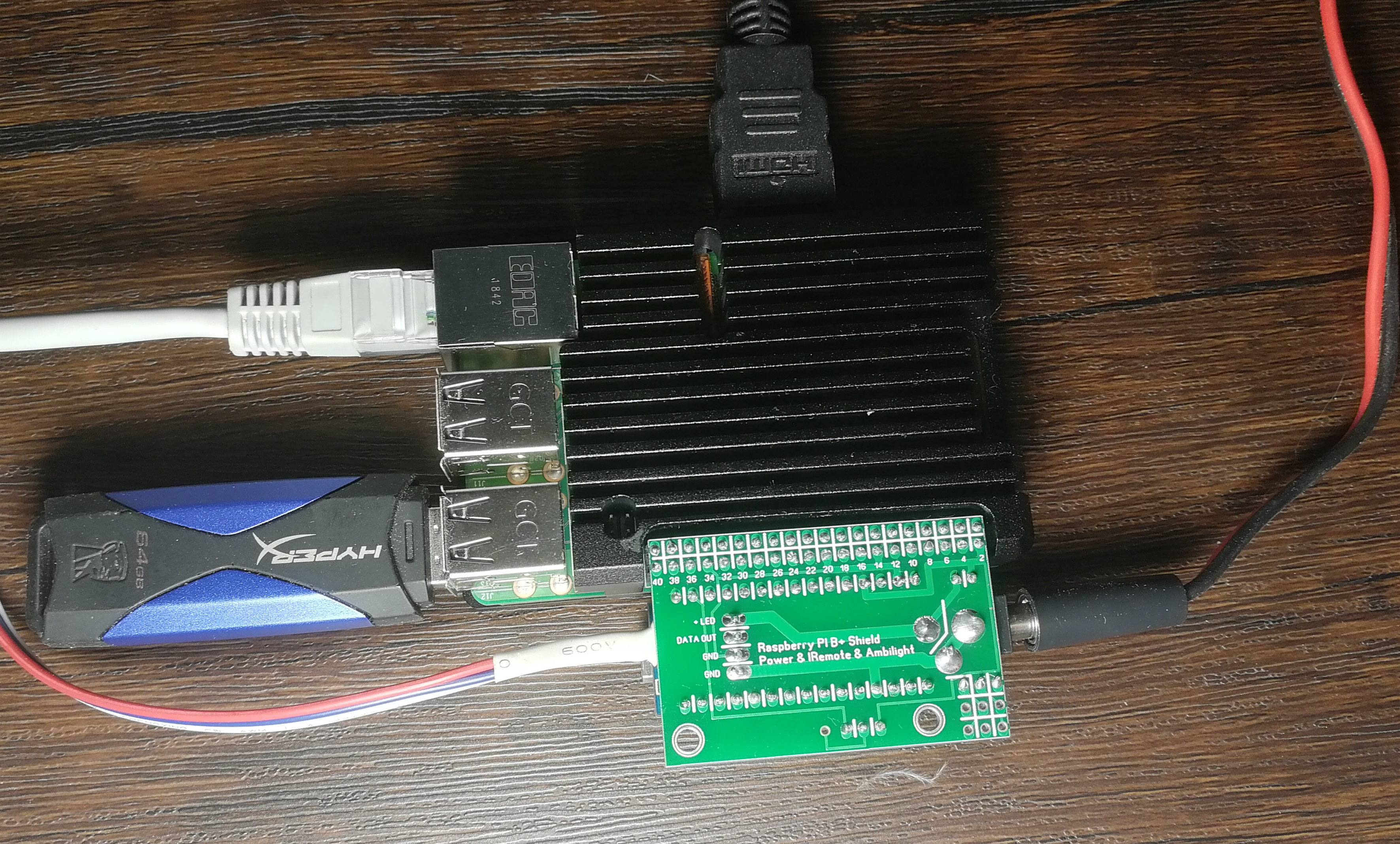
Since the iarduino_IR-master library uses the same timer as some standard “wiring” functions of the Arduino environment, you cannot use micros (), millis (), tone (), and possibly some others in this sketch, otherwise an attempt to compile will lead to an indistinct error. Despite this approach of authors to writing code, the library regularly performs its functions and clearly defines the IR messages, their timings, structure and protocols used, and the ability to quickly read the codes of commands of any console reduces its configuration to a simple replacement of variables in the sketch.The whole superstructure was designed as a shield, for which the following factory boards were drawn and ordered in China: This shield connects an Arduino nano board, a connector for one 5V common power supply, a TV backlight connector, and the shield itself is included in the GPIO Raspberry Pi comb. After assembling all the components, it looks like this: I
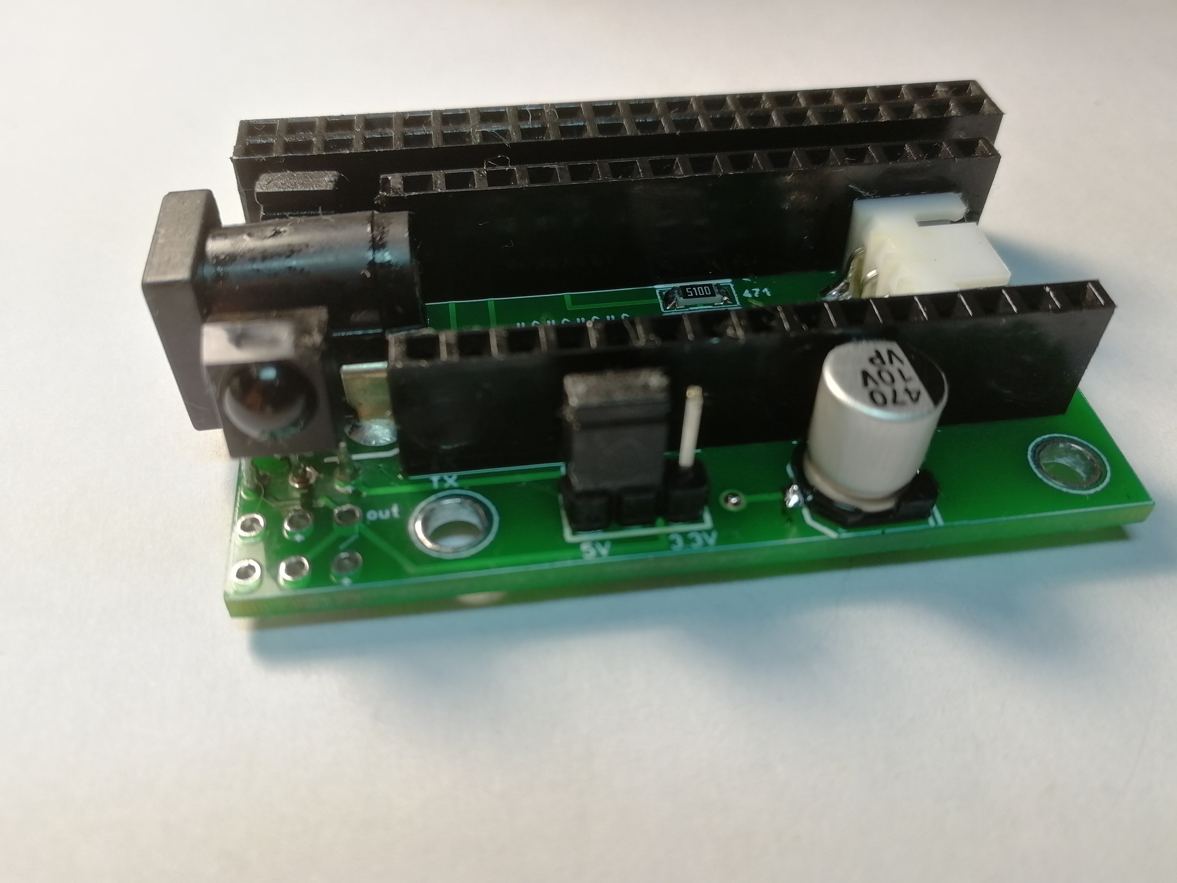
 planned to make a corner acrylic translucent cover on the holes provided for mounting the racks - but somehow my hands didn’t reach, and I still can’t see the set-top box ... Alot has been written about the choice and sticking of the address tape, however, I also have a few comments on this topic and editing.First about myths."WS2812 is not suitable for adaptive backlighting, you need to use SK9822 or even APA102"They justify this by the fact that the data transfer frequency of APA102 analogs is much higher due to the presence of a clock line, and the LEDs themselves have a wider color gamut and are more reliable.All this is true, but if we divide the working frequency of WS2812B by the number of pixels and 32 bits of information for each of them, we get an update frequency of almost 300 Hz for my 91 LEDs. This is several times higher than the required threshold. And all the “flicker” and “idle” cases - 146% are the result of the curve of the wiring of the earth and the signal wire.The color scheme is similar - Hyperion generates 8-bit packages for each color in each pixel. In any case, this is only 256 gradations of brightness of each of the three colors on any tape. The difference in colors will be noticeable only in the calculator on the screen of a good monitor, but the difference in the real glow by ± one or even several gradations our eyes will not see in any case - this is the anatomy of our vision and there is nothing we can do about it. In addition, the configurator has tools for adjusting the color gamut - if you wish, you can achieve almost perfect white color at close to maximum brightness. But even these gestures are unlikely to be needed - the backlight only creates the background on the wall behind the TV, and not the picture on the screen ... When analyzing the capture zones - both Hyperion and Philips take more than one specific point,and the average color of the entire specified area, so the shades will always be something different from those that are reproduced in dynamics at the edges of the screen. Given all this, there’s no point in shooting from a cannon at sparrows, which actually confirms the backlight design in the original Phillips TVs, where only 37 points are displayed on the 50 ”diagonal and the width of the zones is 5-6 cm.Another myth - "WS2812B is short-lived, a month later the pixels began to fail."Naturally, they will begin. Moreover, on any tape. Each color in each 2812B LED at full brightness consumes 18-20 mA. For example, I have 91 LEDs. 91X3X20 = 5.5A. Efficiency is about 30-40%, which means that more than three amperes go into heat. The only effective way to remove heat from the crystal substrates is through the copper tracks of the tape, which is glued to some surface. Connected to power, but the non-luminous tape is also noticeably warm - the chips themselves in static have some current consumption. The back plastic cover of the TV is not the best heat sink for long-term operation of the tape, so it is better and more correct to use a special metal profile. In addition, it comes with a diffuser of various depths, widths and shapes. You will not see reflections in the form of colored dots on the glossy surfaces of the room’s interior,which is also sometimes important.
 When everything is mounted, connected and checked - it remains to configure the KODI player to your taste and color - install all the necessary add-ons, IPTV with program programs and share content from your home PC.If we compare the backlighting with the hardware version - the reaction to the processing of frames seemed more clear to me - there is no sensation of a slight delay in a split second. The implementation itself seems to me quite viable - it turned out to be a simple repeatable constructor assembled by the plug-in principle. If you take care of assembling the switching shield and saving the configured system as an image, it will take no more time to launch another such set-top box than for any “boxed” TV box on android. If you make the IR receiver remote - the device can be hidden behind a TV with a wall mount option. If you have a configured OS or its image, the system will work in full mode the first time you turn it on.For those who watch TV channels, you will have to tinker with their paid and high-quality or free and non-working IPTV playlists, TV programs for channels, add-ons and player settings, which, by the way, has the ability to change skins, of which at the moment there are a great many for any taste. Everything is supported - displaying weather, time, screensavers, hundreds of different add-ons and applications. For example, I wanted to get rid of the OSD non-retractable menu, called for rewind or pause. For this, the add-on - Hide Video OSD perfectly. Download the zip archive, put it in a place convenient for raspberries, select the installation from the archive in the addon interface, set it, enable the addon in the settings, set the time in seconds, after which the OSD will automatically be removed from the screen.In addition to other features, Kodi has a full-fledged web-interface through which you can configure settings, control the player and the media library from your home PC.Publications about all the features of the player, and how, for example, to raise a media server on a PC for Kodi, are easily found in RuNet. For convenience, omnivorousness and other parameters, I would put this player on a par with such projects as WinAmp and MPC-HC.A small demo shot on slippers: